RESISTANCE ©2014 J.D. DANIELS
Electrical Resistance measures how easy or difficult it is for electrons to
move through a material, under the influence of voltage.
We want to start by considering Ohm's Law:
First, let's have you feel comfortable about current. Current is moving charges;
in a wire, current is the charges/sec passing across an internal surface perpendicular
to the axis of the wire. But at this point in the tutorial current is flowing
through a resistor, not a wire.
Unit of current: the amp. Unit of charge: the coulomb. There are
1.602 X 10^19 electrons per coulomb. One volt across 1 ohm passes 1 amp.
In a wire, (and in resistors) the moving charges are electrons. In the case
of wire: the outer shells of metallic atoms. Electrons, since the time of Benjamin
Franklin, have been saddled with having negative charge. All electrons have
absolutely identical charge, but some electrons may have more energy than others.
Is the electron the discrete smallest unit of charge? No, inside of protons
and neutrons there are quarks, with 1/3 or 2/3 the charge of the electron. But
all protons have exactly the opposite (positive) charge of all electrons.
Notice that when a wire has electrons flowing through it (as a current) there
are in the wire an equal number of positive charges (protons) sitting still
watching the electrons flow by.
It will turn out to be important for understanding Ohm's Law that one electron
does not flow in a current at a constant velocity, but bumps into other electrons
and into the atomic nuclei, and thus has a mean free path speed, resulting in
a drift velocity, orders of magnitude slower than the speed of light.
Of interest for BME, in aqueous solutions (not wires) charge can be carried
by Na K Ca Mg etc + positive ions, or by Cl or other negative ions.
[Our specfic consideration of Ohm's Law is current flowing through a (passive
component) resistor...]
Another non-resistor example of current: lightning. In lightning hundreds of
amps of current in the form of ionized air (called a plasma) typically flow
from a thunder cloud to some "desirable" location on the ground.
http://www.youtube.com/watch?v=h0uwpqtjsVQ
video of lightning from thunderstorm over the Black Hills
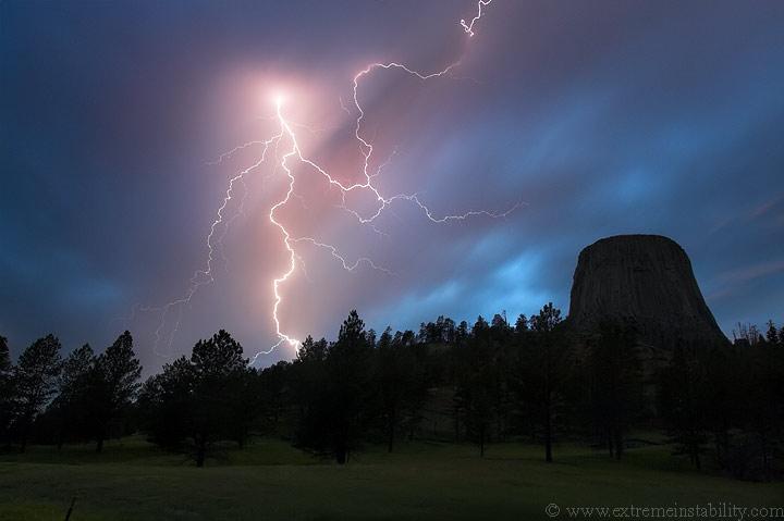 Devil's
Tower WY
Devil's
Tower WY
How fast does lightning travel? About 100,000m/sec or 225,000 miles per hour,
or about 0.03% the speed of light. The average current in a lightning bolt is
about 30,000 amps. Comprising an average of 4 "strokes," a cloud-to-ground
lightning flash lasts anywhere from 100 microseconds to 2 msecs. The average
length of a cloud-to-ground lightning bolt is about 5 miles (8km). Various other
answers can be found, depending on whether the lightning is positive or negative
charges, for example.
A fine way to learn more about lightning: find volume
II of the 1964 book, The Feynman Lectures on Physics, and read chapter
9, "Electricity in the Atmosphere."
Having said all this about charges flowing, we are now ready to answer the question:
Why the heck would charged particles want to flow from anywhere to someplace
else anyway? A one-word answer: Voltage.
Recall from science class that like charges repel and opposites attract. These
notions are expressed in Coulomb's Law:
The E field expresses and inverse-square law. Now if the electric field is known
for a region of space, and one location in space is designated as ground, then
the voltage difference between some other point P and ground G is the
path integral

The unit of voltage is volts; voltage is a scalar, not a vector. Notice the
minus sign in the formula
It doesn't matter what path is taken for the integral, the voltage answer will
depend only on the two start and end points of the integration ("conservative
field")
The voltage is show as ΔV because voltage is always the difference between
to different nodes in a circuit. Often the second node is "ground"
assumed to be at 0 volts, but not always... Therefore Ohm's Law is about the
voltage between one end of a resistor and the other end... the 2 ends of the
resistor being wires with almost zero resistance.
There is a "point" version of Ohm's Law:

where J is current density, and σ is conductivity of the material (conductor,
semiconductor) at a particular point where the E field vector is evaluated.
The point version doesn't isn't practically useful because it doesn't reference
current and voltage. σ is a property of the material in question, which
we will encounter later.
At any rate, to answer the question about why a charges (electrons) would want
to move: Because they feel an electric field caused by an uneven (static) charge
distribution resulting in voltages that "pressure" the electrons along
the way of the wire.
Let us now plot resistance R in the I-V plane:
 http://www.electronics-tutorials.ws/dccircuits/dcp_1.html
The slope of the line is 1/R=G in the plane where I is the vertical
axis. A large resistance would be a nearly horizontal slope.
More possibilities in the I-V plane: a short circuit (0 resistance)
would be a vertical line; an open circuit (infinite? resistance) would be a
vertical line. An ideal voltage source would have 0 Ω resistance; an ideal
current source would have an infinite resistance.
What happens as voltage causes current to flow through a resistance? Power
is dissipated. Power = Volts * Amps. Power (from your physics class) is
the rate of energy use. What does it mean to be dissipated? Electrical energy
is transformed into thermal energy.
The unit of power is the watt. 1 volt sending 1 amp through a 1 ohm resistor
causes the dissipation of 1 watt.
By Ohm's Law you can verify
Any resistor with a little current passing through it will heat up a little...
The common 1/4-watt resistors we have hundreds of in the lab, of a hundred different
values in ohms, are rated to tolerate no more than 1/4 watt dissipation. If
we apply 10 volts to a 100 ohm resistor, and several seconds the resistor smokes
and burns up:
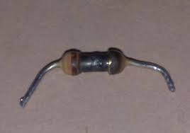 100 ohms
= brown black brown...
100 ohms
= brown black brown...
Power transfer: Look at the circuit below:
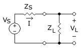
If Zs is fixed, for what value of ZL will the amout of power delivered to
ZL be maximum? (a good quiz question!) For v. small ZL, VL will be tiny, and
for v. large ZL current I will be tiny... Power(ZL) will be max for something
in between...
Resistor color code (3 band): Looked at from left to right the 3 stripes
on a resistor S1 S2 S3 (then a gold or silver stripe for tolerance) are used
as follows: [S1 S2] * 10^S3, where S1 S2 is a 2 digit number between 10 and
99. The color-digit code is the rainbow surrounded by black, brown, then grey
white:
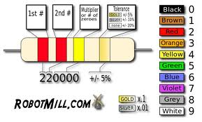 22*10^4
= 220,000Ω
22*10^4
= 220,000Ω
Tolerance: We buy in quantity 1/4-watt, 5% tolerance resistors, (so-called
carbon-film resistors... see
http://en.wikipedia.org/wiki/Resistor
for more detail.) We carry values from 10Ω to 10MΩ, six orders of
magnitude range. The 5% tolerance means the mfgr guarantees that a resistor
labeled as 1000Ω will be greater than 950 and less than 1050Ω ;
the variation follows a gaussian distribution.
Example: at one point in EN123 you will find that the formula for the magnitude
of op amp gain is Rf/Rs; if Rf = 10KΩ and Rs = 1000Ω the gain is
expected to be 10; then the worst cases will be 10500/950 = 11.05 or 9500/1050
= 9.04 gains... not good from a real-world point of view.
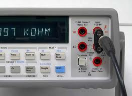
If you sit with a bin full of resistors from the 1000Ω drawer and measure
their resistances with an ohmmeter (your Agilent 34401A multimeter in the lab)
and set aside the resistors in the range 990-1010Ω you will have increased
their value from 3 cents to 25 cents (now 1% tolerance resistors...)
Thermistors: Back to the subject of resistors heating up: Normally we
would like a resistor not to change its value if itheats up (or cools down...).
However, as with all material properties, resistivity (the inverse of conductivity
mentioned above) is temperature-sensitive. If you've had a Materials Science
course you may remember that as a metal heats up its resistivity increases (because
the mean free path of valence-band electrons flowing in metal is reduced). However,
carbon-film and semiconductor resistors experiencing heat find more electrons
moving up to the valence band and thus such resistance decreases.
It's possible to give in to the inevitable change of resistivity as a function
of temperature and look for a material whose resistivity changes a lot with
temperature, then declare it to be a temperature sensor. Such are the thermistors
that you will use in Lab 5 of EN123. A negative-temperature-coefficient (NTC)
thermistor rated at 1200Ω can drop to 600Ω if the temperature increases
from 40C to 58C. Below is a curve from another thermistor (www.arroyoinstruments.com).
Resistors in series or parallel:
In the partial circuit below
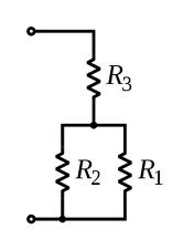
the total resistance is R3 + R2||R1 where R2||R1 = R2*R1/(R1 + R2);
% ------------- -----------------
Voltage divider:
Now consider the voltage divider circuit below:
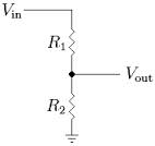
By appropriate choices of R1 and R2 you can set Vout to any voltage between
Vin and 0 (ground).
Potentiometer:
Imagine a circular disk of semiconductor material like you might find in
a resistor, and a spring-loaded "wiper" that can sweep around the
disk and become the center pin of a potentiometer. Schematically what you're
seeing is
 www.fddrsn.net
The total resistance between A and B is unchanged...say RT ohms. Then if R1
= resistance from A to W and R2 = resistance from W to B, we have an adjustable
voltage divider. If A is connected to Vin and B to ground, then
A circuit symbol for a potentiometer is

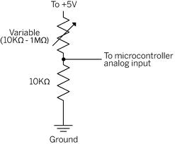
Note 1: Suppose Vin at pin A is a significant voltage, say 25 volts.
In the circuit below the lowest the potentiometer wiper can be is 2.5v if the
potentiometer is turned down to 10K..:
 (www.tigoe.com)
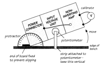
Note 2: A potentiometer with its shaft controlling the angular position
of the wiper is a rotation sensor. The wiper position can be proportional to
the angular position of the shaft. See below:
 (stemeducationreferences.pbworks.com)
Conductance. For resistors in parallel it is more convenient to consider
them as conductances. Conductance G = 1/R and has the unit of mhos. (Or
siemens, in Europe). Two conductances in parallel have a combined conductance
of GT = G1 + G2.
The most studied parallel conductances in biology are the voltage and transmitter-sensitive
protein channels in the membranes of nerve cells. (ref Bertil Hille, Ion
Channels of Excitable Membranes 3rd Ed., Sinauer, 2001).
As a conductance challenge (and because we will encounter ladder circuits twice
in EN123) consider the particular resistive ladder built up below: Say each
of the resistors in the circuit is of value R. From the upper left node to ground
what is the conductance?
G is in parallel with 2R = G/2 to ground so the total conductance is GT = G+G/2
= 3/2 * G
Now add another segment to the ladder:
What now is the conductance from the upper left node to ground?
Add yet another segment to the ladder to find
The sequence of terms multiplying G is continued by: (in one line on Matlab)
v6 = [ 1 8 21; 1 5 13] , for ii = 4:7 v6(2, ii) = v6(1, ii-1)+v6(2, ii-1); v6(1,
ii) = v6(2, ii)+v6(1, ii-1); end, v6, v7 = v6(1, :)./v6(2, :)
converging (after skipping every other term...) to the famous Golden
Ratio number of 1.618... well, that was fun!
Kirchoff's Current Law (KCL). Graphically, a circuit consists of nodes,
and branches connecting the nodes. For now the branches can contain resistors,
or voltage sources or current sources. Later in the branches we'll allow capacitors
and inductors, and diodes, oh my.
Kirchoff's Current Law says: The algebraic sum of the currents into a node
equals zero. By "algebraic" we mean that you--the analyzer of
the circuit--have drawn arrows on the branches indicating which way you think
positive current is flowing. If the actual current is flowing in the opposite
direction from your arrow then the algebraic current is negative. Remember that
because electrons carry negative charge a flow of electrons in a particular
direction in a branch is a negative current.
 www.faqs.org
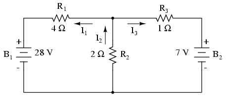
In the circuit above the current direction arrows are drawn for the one node
whose voltage is unknown. The bottom node can be assumed at 0 volts (ground,
reference). The nodes at the upper left and right are seen to be at 28v and
7v because of the voltage sources.
Once the current arrow is drawn the dwg below shows the convention for assigning
+ and - to the voltage across the resistor Rr:
 www.facstaff.bucknell.edu
To write KCL for the nodes in a circuit we have to agree on one more convention:
For "positive" results it is this: If current is flowing out of the
node it is positive; flowing in, negative. Also appreciate
that the conductance version of Ohm's Law is I =G*V.
Now we can write KCL for the unknown-voltage node VN in the 2-voltage-source
circuit above, where we have:
Node admittance matrix. The canonical problem of EN52 (or any introductory
circuits course) is this: Given a circuit with N nodes, and connecting branches
(containing R, C, L elements or voltage or current sources) find all node voltages
and all branch currents. One of the nodes will be easy: the node designated
to be reference, and set to 0 volts.
Otherwise, here is what to do (at least to begin with...): Write out KCL for
each of the other N-1 nodes. In writing out KCL you will have drawn arrows for
the positive direction of current. You will use the convention that + is on
the tail of the arrow going through the branch element, and (-) is on the arrowhead
side of the element. Further, agree with me that currents going into a node
count as negative and leaving a node, positive, in KCL.
You will have N-1 equations in N-1 unknowns (the non-reference node voltages).
Because (for resistor-only circuits) your KCL expressions will be of the form
G*V = I, (the word "admittance" is a generalized form for conductance)
you can express your KCL equations as Yn*V = Is, Yn is the node admittance
matrix, V is a column vector of node voltages, and Is are current sources in
circuit. The answer to the node voltages is
Before illustrating the idea above with a specific multi-node circuit, we need
to make a remark about current and voltage sources. Current sources are straightforward
for KCL: They contribute directly to a current going into or our of a node.
A voltage source where one of its ends contacts the reference node, then the
other end contacts a node directly, with no series resistor... then that node
can be taken out of the KCL list. If the voltage source is in parallel with
a resistor, that resistor can be taken out of the circuit. (Why?)
Otherwise you must convert voltage sources to current sources:
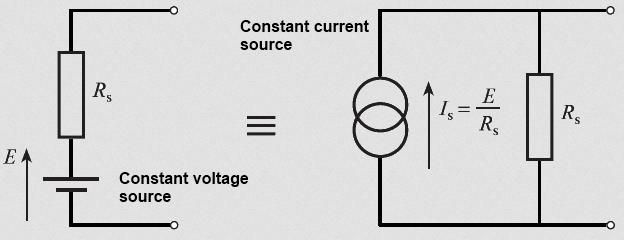 myelectrical.com
The voltage source will be in series with some
resistor Rs; the equivalent circuit with a current source has Is = Vs/Rs amps
and Rs in parallel with the current source.
Such a change is also know as a Thevenin-to-Norton transformation. In
general any two points in a resistive network can be reduced to either a Thevenin
(voltage in series with a resistor) or Norton (current in parallel with the
resistance) circuit. Measure the open circuit voltage and the short circuit
current of the the two nodes to model, and the calculation of the ideal voltage
source (0 resistance) or the ideal current source (open circuit) + the accompanying
resistor will be straightforward.
Having said all this let's tackle the resistor ladder, now with a current source
on the left and all the resistors different, and shown as conductances Gx:
The arrows for assumed direction of currents are shown in red. The 4 nodes with
unknown voltages are numbered. KCL equations for the nodes are (with current
out of a node as positive):
and now the beauty of the node admittance matrix: you don't need to write out
KCL for each node. You can write down Yn by inspection: the diagonals are the
positive sums of the conductances touching the nodes in question; the off-diagonal
terms (i, j, i not = j) are symmetric and are the negatives of the conductances
between nodes i and j.
I once wrote out the above and announced to a class that it was an example
of the node admittance matrix method. A student in the back raised her hand
and said in her perfect South Carolina accent, "That's not an example.
Those are just letters. An example has to have numbers. You don't have any numbers
on the board!" So taking her definition of an example, let's says the *resistances*
in the circuit are 1Ω for G1, 2Ω for G2...7Ω for G7 and let'
say Is = 8 amps.
Using Matlab and transcribing...
G1 = 1; G2 = 1/2, G3 = 1/3; G4 = 1/4, G5 = 1/5, G6 = 1/6, G7 = 1/7,
Yn = [G1+G2 -G2 0 0; -G2 G2+G3+G4 -G4 0; 0 -G4 G4+G5+G6 -G6; 0 0 -G6 G6+G7 ]
Is = 8
Then we have
After finding that the determinant of Yn is non-zero, the next two lines of
Matlab code would be
Ivec = [Is; 0; 0; 0]
Vn = inv(Yn)*Ivec
(c:/MatlabR12/work/fold23/NodeAdmitExample.m)
You will see the node admittance matrix in action in 123 when we analyze the
VCVS active filter for Quiz 2.
% ------------- -----------------
Using Superposition
to help solve linear circuit problems: While the node admittance matrix takes
care of all inputs at once in solving a circuit for node voltages, it is possible
to appreciate superposition (linear summation) as a way to break a circuit up
into smaller problems. Using superposition means that all but one input (IN-now)
should be set to 0, and the influence of IN-now on all (or the one of interest)
node voltages is calculated. To set a pure voltage source to 0, turn it into
a short circuit (to ground); to set a current source to 0 make it an open circuit.
Then the answer to the full circuit problem of many inputs
is the (vector) sum of the individual input (In-now) problems. Superpositition
will be used a couple times in EN123 to look at the result of more than one
input (e.g. D-A conversion) being active for a circuit.
Definition: For a linear time-invariant circuit (one
with resistors and voltage-source inputs for example) having one output,
the separate output values due to each input one at a time all add up to the
output value when all inputs are active at once.
An example of a non-linear system: one whose output
is the square of the sum of two inputs A and B: A^2 + B^2 does not equal (A+B)^2.
2^2 + 3^2 = 13, but (2+3)^2 = 25...
Below is an op amp circuit from an EN123 Amplifier
Quiz. Given values for K, and the 3 V inputs, the most efficient approach would
be to calculate each output due to ONE of the inputs V1, V2, V3 active (and
the other two grounded...) then summing up those 3 numbers for answer.
In the Linear Systems course (EN157) for EE majors there
will be a formal proof that a system (with say one output) is linear by showing
that the sum of outputs due to one input at a time is equal to the output due
to all inputs acting simultaneously.
Wheatstone bridge. The most frequently used resistor
network in EN123 will be the Wheatstone bridge. For example, here's a Wheatstone
bridge from a recent strain gauge quiz:
The Wheatstone bridge in the circuit above is two voltage dividers side-by-side;
the bottom of the bridge is grounded and the top is connected to an "excitation"
voltage. Comparing the two center points of the dividers is a differential amplifier
of gain G. If all of the resistances in the bridge are equal then the two divider
outputs are equal and the output of the amplifier is zero. However, if (say)
the "bottom-longitudinal" resistor is slightly greater because it
is strained in its location, then the left side of the bridge will have a slightly
higher voltage and Vout will be an amplified voltage of the cross-bridge voltage
difference.
If you use 5% tolerance resistors from the drawers in the lab to make a Wheatstone
bridge it will certainly be unbalanced. Strain gauge resistors are basically
$10 precision resistor sets that are guaranteed to be within 0.1% of (say) 120Ω
in their "un-strained" state.
It's important that the un-strained state of the bridge be balanced so the
output of the diff amp is 0 and the gain of small non-zero differences can be
as high as possible...
If we abbreviate the 4 resistors in the circuit above as RTT, RBL, RTL and
RBT then the output of the amplifier with gain G is
Note: in the strain gauge example above passing current through the (metallic)
strain gauge resistors will heat up the resistors slightly and their resistance
will increase slightly...but because all 4 resistors in the bridge are changing
together the Wheatstone bridge will do a good job of compensating for ambient
temperature change.
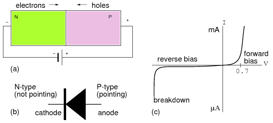
Diodes and rectifiers: The current-voltage relationship
of a resistor is linear. A semiconductor diode has a nonlinear relationship
which makes it seem like a "one-way wire" or rectifier. The
equation describing the I-V relationship is
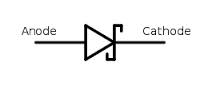
where ID and VD are diode current and voltage respectively. The symbol for such
a diode is at the bottom right below
 www.allaboutcircuits.com
and on the right side above is a plot of the current-voltage relationship for
a doped-silicon diode.
VT = kT/q = 25mV, at room temperature, where T is in degrees Kelvin,
q is the magnitude of charge on an electron and and k is Boltzmann's
constant.
A diode is a voltage-sensitive resistor. (note slope changes in the V-I curve).
In the lab we have a drawer full of 1N914s, a common silicon P-N junction diode.
Given the formula we have for diode current and a function of diode voltage,
what happens to the resistance of the diode (ΔV/ΔI) if VD = 1
volt and temperature increases? Yes, it seems that diode current decreases,
so resistance must increase, which is incorrect for the semiconductor materials
a diode is made of...the paradox will be solved in the lecture on temperature
transducers, due in October.
A diode is rated by how much current it can handle. At 25degC a 1N914 can handle
a maximum of about 90mA in the forward direction.
A silicon diode is not a perfect rectifier, which would be open-circuit for
VD < 0 and short-circuit for VD>0, but it does well, and can be made "perfect"
as feedback element with an op amp (more later...).
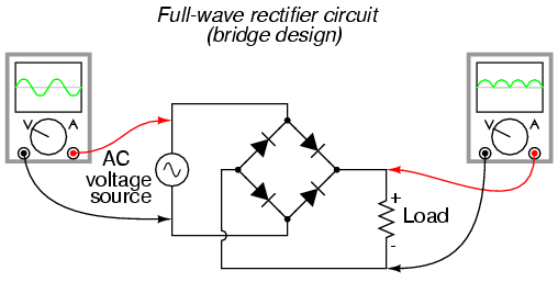
In a full-wave rectifier (absolute value circuit) 4 diodes are arranged
like:
 forum.allaboutcircuits.com
When the AC input is greater at the top than the bottom of the "bridge"
then current passes through the upper right diode, then down through the Load
Resistor, then back through the lower left diode to return; when the AC input
is the opposite phase the other two diodes form the current path, but the +current
still moves from top to bottom of the Load resistor.
Notice that the minus side of the load is NOT connected to he minus sign of
the AC input.
We'll see later that a full wave rectifier is one part of a DC power supply.
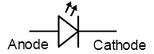
Diodes have other forms and uses: Light Emitting Diodes (LEDs) properly
fabricated can emit light in a variety of colors; LEDs have forward bias voltages
in the range 1.3-1.8v, much greater than the 0.7v of a 1N914 type diode.
Demo: A DMM in the "diode" shows the forward bias voltage: 0.7
for P-N doped silicon junction, 1.7 for a red LED
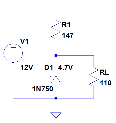
Zener diodes have calibrated reverse breakdown voltages; zeners are
used to limit and regulate voltages. The circuit below shows a zener diode holding
the voltage on the load resistor to 4.7 volts.
 mechatronics.colostate.edu
A Schottky diode has a smaller forward bias voltage (0.3v) than a regular
diode, and has faster switching times.
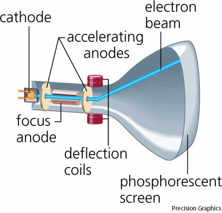
Ohm's Law redux: electron beam current in a cathode ray tube.
This tutorial began with us wanting to contemplate Ohm's Law, V=I*R. Ohm's
Law only holds for Ohmic materials. Certainly what constitutes a diode does
not qualify as Ohmic... another example: the electron current flowing in a cathode
ray tube. A sealed cathode ray tube contains no material: a vacuum is pulled.
 images.yourdictionary.com
An old-fashioned television or computer monitor! A heated cathode boils off
electrons that are pulled toward the screen by 25,000 volts on the accelerating
anodes. To find the E field from voltage use the gradient operator: 
Inside the vacuum the electrons in the current have a chance to obey Newton's
First Law : Force = Mass*Acceleration. Recall Coulomb's Law says F = q*E, where
E is the electric field at the point of charge q. Near the cathode the electron
density is great as the electron "drift" speed is low. Later as the
electrons accelerate in the electric field, they spread out and their density
decreases. Yes, the current dQ/dt stays the same, but the electrons are accelerated
closer to the speed of light. Ohm's Law doesn't apply for the electron beam,
which has more in common with a lightning bolt.
In a resistor there are atoms that the "drifting" electrons bump
into that divert and slow them down, much like a skydiver eventually reaches
a terminal velocity of 120 MPH before opening his parachute. Here Ohm's Law
rules, because the electrons in the resistor are traveling about the same speed.
(A rather elaborate solid state physics explanation is needed to show that while
the drfit speed (as low as 1m/sec) of electrons is v. slow the reaction in the
circuit is much faster...)
In the next tutorial, on Capacitance, we'll see another realm that Ohm's Law
doesn't account for.