Lab
1: Gain-Bandwidth Product in LF353 op amp
Background: The
op amp is probably the most important analog circuit building block. In EN123
we'll see op amps in the service of frequency filters, so-called active filters.
Frequency specification is important for any op amp, and in this lab we will
investigate the LF353 op amp's frequency response by measuring its gain-bandwidth
product (GBWP).
The actual gain of an op
amp circuit times the frequency of its input signal must be less than the op
amp's GBWP.
http://www.ti.com/product/LF353-N
Requirements:
(1) Build an op amp circuit with a gain of -10. Test your circuit by showing
that an input of 0.1v results in an output of -1.0v. Activate
the Track feature of the triple-output power supply for your +/- 12/15v needed
at supply voltage pins 8 and 4 on the 353...
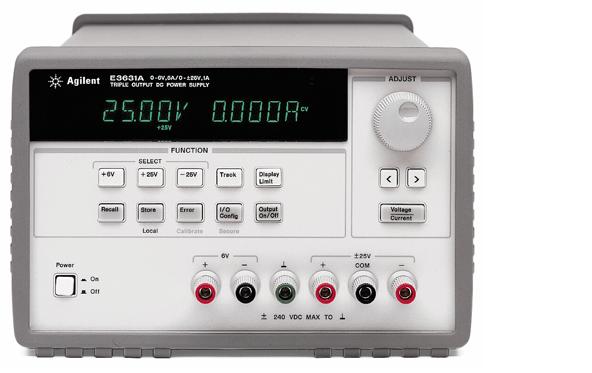
The black COM for +/- supply and the black "-"
with the 6v supply should be connected together; it's not necessary to connect
them both to the green "ground" terminal. You'll have 4 wires running
out to your circuit: +12/15, -12/15, COM, and 6v+ (variable Vin); pick different
colors for each wire and braid them together for a neater circuit!
(2) Use the 54622A oscilloscope
to observe from the
Agilent 33120A waveform generator a 10KHz sine wave with a peak-to-peak signal
of 0.5v.
(3) Show that when the sinewave
is used as the input to your gain of -10 circuit, the output is a 5v p-p sinewave,
gain of -10. Watch both the input and output to the circuit to see that the
waveform is inverted.
Warning:
Do not connect the output of the 33120A directly to a power supply output or
the 33120A output may be damaged, or an output fuse may blow. The
output fuse is hardwired to a PC board inside the box, and is a... a difficult
part to replace.
Note
on Menu D of the 33120A you can change the termination from 50 Ohms to High
Z, so the peak to peak reading from the instrument agrees with the value seen
on the scope.
(4) Next increase the gain
to -100. Use a p-p input of 50 mV for you sinewave input. To have a 50mV p-p
output from the function generator, you will need to run a 50 ohm resistor to
ground where the sinewave goes into your op amp input. At 10KHz input, You should
see on the oscilloscope a 5v p-p output of the sinewave, inverted.
Gradually increase the input
frequency until the gain falls to a value of -50. What is the frequency? Multiply
the frequency by 50 you have your op amp's GBWP. What does the data sheet say
the LF353 GBWP should be?
(5) Now build an op amp circuit (one op amp only) with a gain of +10
(input to the +V pin) and reassess the GBWP. Measure also for a gain of +100.
Your positive gain op amp will be governed by
as seen in lecture and in the online notes.
Enter your GBWP answers in
Word, in your student work folder. Be prepared to demonstrate any of the GBWP
experiments above.
(6) Find an electret microphone
and its data sheet (such as DigiKey part 359-1007, from Horn Industrial Co.)
and use it as an input to a high Zin positive gain op amp. The mic's have been
wired: orange for signal and green for ground. The signal connection must go
through a 500 - 1000Ω resistor to a 1.5-2v supply.
link
to site discussing sound level measurements in decibels
Whistle or sing into the (1.5v
powered) electret microphone and observe the output of the op amp on your 54622A
'scope. Increase the gain of the op amp until you can produce an oscillation
on the scope greater than 1v p-p. (whistling or singing, not hand clapping...)
You will likely
need to eliminate the 1 volt or so that is a DC component of the signal in order
to amplify the oscillating component without saturating the output. Try a C-R
high pass filter (0.3 μF and 1MΩ) or try subtracting 1.2 volts with
a negative gain summation amplifier.
Do Lab 1 with your partner.
Possible FTQ: With a particular
input frequency in the range 100K to 1MHz, and your op amp wired for gain of
-100, what will be the output amplitude?
Free Advice: On your LF353 note which is pin 1 (bottom left pin when
you can read the print on the chip). Push the chip pins into holes across the
channel on a of white solderless breadboard. You'll need to use the Tracking
feature of your triple output power supply to provide ± 12-15 volt power
to the chip. You may want to review the first few pages of
Lab 1 (2001) on the EN123 archive website.
On the Agilent 'scope make sure that for each channel
"Probe" says "1.0 : 1", meaning that your are using straight-through
connectors, and not X10 probes (in the pouches on top of the scopes) for stimulus
and response recordings.
Also look at Lecture notes on Amplifiers from the homepage, or see the archive
lecture notes from 1999.
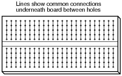
White Solderless Plastic Breadboard: The holes in the top horizontal row of
the breadboard all lead to the same conducting "clip" underneath;
ditto for the bottom row. The horizontal columns are connected as shown below:
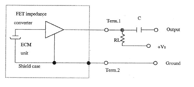
MICROPHONE: See below for snapshot from Horn
part 359-1007 pdf datasheet, found through digikey.com: (2011: microphone
668-1196 from digikey)
You can let your capacitor
be 0.3 muF, from the reel near the emergency shower in 095. Where the capacitor
contacts the V+ pin of the op amp run a 2MΩ resistor to ground,
so the isolated capacitor doesn't cause op amp output to saturate. RL can be
500-1000Ω. "Output" below is the output of the microphone...
If you haven't used an oscilloscope before, ask JD or the TA for a brief introduction.
Another possible FTQ: Show how, using two diodes and 4 op amps, you
can make a full wave rectifier for a sinusoid input. In other words, an absolute
value circuit... hint: see amplifer notes about