Lab
2: Common Mode Rejection Ratio in AD524 Instrumentation Amp
Background: The
LF353 dual op amp chip costs about 50 cents. The AD524 is more like $18 per
chip. Why the difference? One reason, a better GBWP, 25MHz vs 4MHz. Another:
better CMRR, Common Mode Rejection Ratio: Common mode means that the two inputs,
V+ and V-, to the amplifier are connected to the same input, say a 1v p-p sinewave.
Now if the amplifier is truly differential, the output should be exactly zero.
But, as you'll see, it isn't. It is small, but not zero. Suppose a differential
gain G, of 1000, where Vout = G*(V+ - V-), results in an output of 1 mV p-p
when both inputs are connected to a 1v p-p sinewave.
The ratio (common-mode)/(differential-mode
gain) = 10e-3/10e3 = 10e-6, = 0.000001, or -120 dB, in this example.
Requirements:
A. (0) Find the pinout of the 524AD, from the Analog Devices website.
The 16-pin 524 chips have gold leaf and are in green
sockets, in a cup on a shelf near the sink...
(1A) Note which is pin 1 (bottom
left pin when you can read the print on the chip). Push the chip pins into holes
across the channel on a piece of white solderless breadboard. Connect it to
power, taking care to wire +12/15 to pin 8 and -12/-15 to pin 7 (and not
the other way around!) Figure out what to connect pin 6 to. Strap the OUT
pin to SENSE (pin 10). Connect pin 3 to another pin that will give you a gain
of +10. Show that with the positive input pin at 0.5 v the output is 5.0 volts
(minus input grounded).
(1B) Increase the gain to
100. Use the Agilent
waveform generator to send in a 1KHz sinewave of p-p amplitude 100 mV to the
positive input pin, while grounding the negative input pin. What is the p-p
amplitude of your output? Use your 54622A digital 'scope. Display input
and output simultaneously, to make sure the gain is positive.
(2) Increase the diff. mode
gain to 1000. Now send a 10v p-p 500 Hz sinewave into both pins 1 and
2. Since both input pins are connected together, they are in the common mode.
What is the p-p magnitude of the 524 output? (If the 524 completely rejected
the common mode the output would be exactly zero.) What then is the common mode
gain? Compute the common mode rejection ratio = CMRR = common mode gain/diff.
mode gain, and convert to dB scale (20 log10 (G)). Change the input frequency
to 50KHz and repeat the measurement. What happens to the CMRR? What does the
data sheet say we should expect the CMRR to be?
(2b) GBWP:
With the 524 gain strapped at 100, explore actual gain with the sinewave
+ input frequency up to 1MHz (amplitude at 100mV p-p) and the minus input
grounded; measure the actual gain. What then does the result imply the gain-bandwidth
product of your 524 is? (even though you don't test with an input greater than
1MHz...)
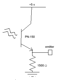
(3) Hook up 2 direction-selective light-sensing PNZ-150 phototransistors in the
common emitter configuration. See diagram below. If the lens is facing you, the
emitter pin is on your left...
Place the two PNZ-150s on one end of your breadboard, pointing about 30 degrees
apart. Aim them so they look at a light bulb from different angles. Examine
the emitter output with the PNZ-150 under fluorescent or incandescent light,
using your digital 'scope. Can you see flicker in the waveform? Its frequency
should be 120 Hz, not 60Hz. Why?
Notice not much amplification
is needed to see the PNZ-150s in action.
(4) Set the gain of your 524AD
to 10X. Now send one PNZ150 emitter to pin 1 of the 524, and the other emitter
to pin 2(+ in) of the 524. The common signal should include the 120Hz flicker,
so what you should see is a 10x amplification of the different light
levels seen by the 2 photo-xsistors. How much common mode "leakage"
can you see in your 524 output?
The output of your differential
circuit can be used to determine at what angle a distant light source is, w.r.t.
a line perpendicular to a line joining the 2 PNZ-150s.
(5) Display on a LabVIEW chart
graph the continuous analog 524AD output response to changing light; let the
display be a strip chart view of the most recent several seconds.
Read about charts in the online
Users Manual: Go to
Help/Find Examples/Fundamentals/Graphs and Charts/Control
References.vi
for a LabVIEW
2013 VI with a charting example.
Possible FTQ: Your FTQ will involve the photodectector circuit: blocking
off light to one of the photoxsistors. You should explore what happens to the
DC or AC components of the 524 output when block off one or the other of the
PNZ150s.
Free Advice: Find the pinout of 524AD at the website www.analog.com,
searching by part number. You'll see on the data sheet what the official CMRR
is. Watch out when you wire up power to the 524: the ground and +15 and -15
supply pins are right near each other! You'll need to use the Tracking feature
of your triple output power supply to provide ± 12-15 volt power to the
chip.
Work on your circuit with the power off...if you reverse the power to the chip,
and turn the power on, you might see a small puff of smoke from the chip: it
will have burned out, irreversibly.
You may want to review the first few pages of Lab
1 (2001) on the EN123 archive website.
For more information about instrumentation amplifiers, see the lecture notes
on Amplifiers.
If the PNZ 150 phototransistor lens is facing you, the
pin on the right should go to +5v and the pin on the left should go to ground
through a 1.5K resistor. The output is the (emitter) pin on the left.
New for 2014: Panasonic has gone out of the photox business...
We now have Rohm RPM-22PB phototransistors [digikey part 511-1354], in addition
to the PNZ-150s. The 22PB generates a reasonable output with a 16K resistor
to ground on the "emitter." The 22PBs are black and are screwed into
black terminal blocks with red wires on "right" side to go to +5v,
and the 16K resistor coming off a screw on the "left" side (you facing
the lens of the 22PB).