Lab
3: Ground, Ground Loops, and Ground Fault Interruption
Background:
A 3-prong power
outlet has slots for Hot, Neutral and Ground (Black, White, Green).
Hot and Neutral carry current to and from the load, be it the load light bulb,
power supply or motor.
Ground should carry no current.
Ground is there for safety reasons, for shielding, and for a stable voltage
reference.
In this lab you will look
at ground vs neutral, induced voltages in loops of ground wire, and how a circuit
can detect a leakage current fault on the ground wire, and open-circuit the
hot path as a result. (GFI)
Requirements:
Start with a Lab 3 box, which is be plugged in from two power cords, and which
has front panel terminals for each power cord's neutral and ground. Also in
the box is a pathway from one hot (left, yellow plug) to ground through a pushbutton
switch and a variable resistor.
(1A) Measure with the DMM
voltmeter, on the AC setting, the voltage between neutral and ground.
Measure gnd vs neut at one outlet, and with gnd from one outlet and neut from
the other. Record your answers (perhaps in Word, in your EN123 IP folder). Compare
to the voltage between ground and ground. Why the the neutral-to-ground voltage
greater? Remember, where power comes in to the building
from the grid neutral and ground are connected together (before taking seperate
paths in the wall wiring).
(1B) Now turn on the 2.5A
the drill press. Does the neutral-ground AC voltage (ON THE RIGHT SIDE
POWER CORD JACKs--the one in the same plug strip as drill press) difference
increase, decrease or remain unchanged? Record the values in mV. Ask JDD
to grip in place the chuck THEN turn on the drill press. What is neutral-to-ground
AC volts now? Why is it different?
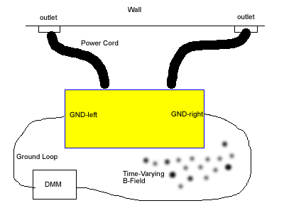
(2) Example of Faraday's Law:
Place the voltmeter (AC) between the two ground outlets on the box. You
will have formed a ground loop with a voltmeter in series. The ground
loop extends from one connection of the DMM to the Lab 3 Box, through one outlet,
to the other outlet, back to the box and back to the other DMM connection. See
diagram...
What is the voltage across
ground? (we hope it is less than a mV!) Record and label your answer. You may
want to connect a 1µF "orange drop" capacitor across the ground
binding posts to see if it can fitler any "non-60Hz" noise that may
be contributing to the AC voltage...
Now turn on the mixer and
move it from a distance to inside the "ground loop". Record what is
the AC voltage away, near, and inside the loop. Also try stradling the mixer
over one of the ground loop wire "borders". With what arrangement
of the mixer and the ground loop is the induced voltage greatest? B
field is a vector. How does your induced voltage depend on the orientation of
the mixer?
Connect the
ends of a coil of wire (on a spool) across the two probes of the DMM, on AC
volts: note the voltage is zero if no AC magnetic field is present. Move the
coil around a stationary mixer to see how the coil might be used as a detector
of (changing) magnetic field. How large a voltage can you measure?
(3)
Plug the left side of the Lab 3 box into the GFI outlet. On the box is
a switch that will route HOT through a 75K Ohm potentiometer in series with
a 4.7K fixed resistor. The other end of the resistor connects to a banana outlet
on the front of the box.
Place
your DMM, in AC current mode, in series with the Hot-out to ground, to measure
the current in the ground fault. You will need to put one lead in the lower
red banana socket so the current is routed through the proper path in the DMM.
Remember to take the current lead out and put it back
in the voltage socket at the end of the experiment, or we may blow a fuse in
the current detection path.
On
the front panel of the Lab 3 box hold down the pushbutton on the left, turn
the potentiometer knob CCW and ncrease the ground fault current until you hear
a pop and the GFI disengages the hot wire. How much current was flowing to ground
when the GFI activated? Write down the answer in mA.
Press
the RESET button on the GFI to repeat.
What
happens if you turn on the 2A drill press while the ground fault current is
increasing?
What
happens if you plug the GFI outlet into a 2-prong "cheater"? Can you
see any ground fault current? (disconnect the coupling capacitor between the
grounds)
Reading: Read chapter 14, by Olson, of the Webster book (handed out,
and on 095 bookshelf...), and website lecture notes on Elec Safety.
FTQ:
Explain how a standard GFI circuit works. You'll want to say what a ground
fault is, how a GFI can detect it, what the GFI circuit does to stop the ground
fault current, and what happens before the manual reset button is... key
words for your "speech". Please do not begin any sentence you
speak with the word "So". Only Prof Daniels
or Prof Borton can sign off Lab 3.
optional: Calculate the RMS magnitude
of 60 Hz magnetic field in a ground loop, given the area of the loop
and the RMS AC voltage recorded from the ground loop. For example, from a search
coil to measure eye movments. Use Faraday's
Law. The dot product B(t)•a is a term to consider. Assume the B
field is parallel to the area vector. Name the unit of magnetic field strength
used in Faraday's Law.
scoring: minus 1 point for taking longer than 15 minutes
on your FTQ. Plus 1 point for taking less than 5 minutes.