Lab4
Lambda : Reading Phototransistors on ADC Inputs: Logic for Rotation toward Light
Source
A-path Lab!
Background: Here
you will use the two DAC channels on the 6024E card to send analog signals to
a microprocessor: either the MSP430 or Aruduino. The analog signals will simulate
the output of two phototransistors. It will be imagined that PNZ150 phototransistors
are responding to a distant light source, as they did in Lab 2. Based on the
sum and difference of the two analog signals, the code will orient the (simulated)
rover to point toward the light. In essence, the phototransistor signals will
act as FEEDBACK for navigating the rover to knock over a block under the lamp.
(You
are required here to upgrade your Lab4pre VI to handle 2 analog INs. Demo on
the LabVIEW "exercise" VI that your new code logic works to respond
properly to phototransistor signals difference and sum.)
(1)
"Upgrade" your Lab4pre to add two analog-out sliders: See suggestion:
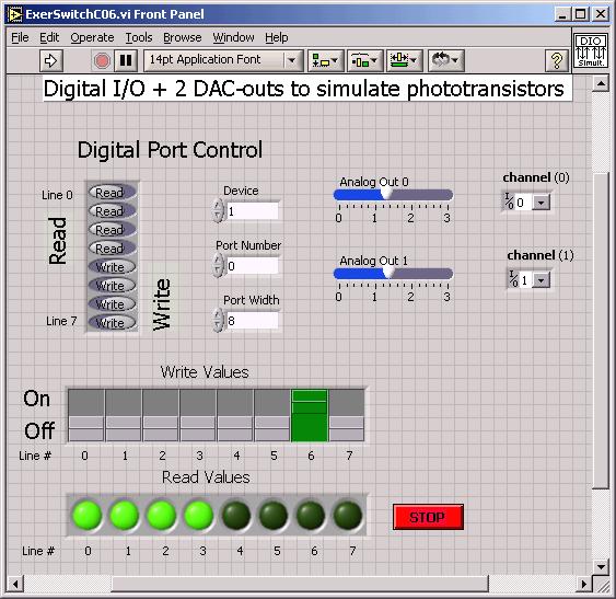
the sliders will have a range of 0-3 or 5 volts: your Arduino code can handle
up to 4.8v.
The LEDs L0 to L3 represent what they did in Lab4pre:
L0
ON left wheel going forward; L0 OFF left wheel in reverse
L1 ON right wheel
going forward
L2 ON left motor turned ON; L2 OFF left motor inhibited
L3
ON right motor turned ON
The switches
D4-D6 act the same as they did in Lab4pre:
D4 ON implies rover is in contact with left wall
D5 ON implies rover is in contact with right wall
D6 ON means the timed loop is activated inside the infinite loop of the code.
(Flick D6 so the rover goes through only one cycle of 25-40 sec)
First, declare
int photoL, photoR, thet_diff_LO, thet_diff_HI, thet_summ_LO,
thet_summ_HI;
signed int diff, summ;
These lines declare variables for the A-D conversion.
We suggest you compute:
diff = photoL
- photoR; // difference of photoxsistors
summ = photoL + photoR; // sum of photoxsistors
Figure out reasonable threshold
values for further logic considerations:
thet_diff_LO
thet_diff_HI
thet_summ_LO
thet_summ_HI
You may want to run the slider at 1v, 2v, 3v, 4v to see
how those voltages are represented inside Arduino.
Make sure
you see the following connections of LabVIEW connector card to socket/Arduino
demo board:
DAC-OUT-0 screw 22 to
blue socket pin 25 to Arduino ANALOG pin 0 Left
phototransistor/slider
DAC-OUT-1 screw 21 to blue
socket pin 27 to Arduino ANALOG pin 1 Right phototransistor/slider
Green GND wire of blue socket to pin 53 (GND) of the
LabVIEW connector card.
----------------- ------------------ -----------------
Arduino:
Running the 4pre default code with the serial terminal turned on you can see
the 4pre code already finds the two "phototransistor" sliders and
displays them. Follow through on the advice below to set thresholds. As before,
immediately rename the default code and take off the "read only" option.
Modifiy the renamed code to meet the specs of 4 Λ
Note
that analog_out pins 21 and 22 (controlled by the sliders) on the green NI connector
board go to ANALOG pins 0 and 1 on the Arduino board. On the white breadboard
are 1.5K resistors to ground for when the board is plugged into an actual rover.
(3) Modify code inside
your pp < pp_max timing loop such that (in psuedocode):
(i) If summ < thet_summ_LO
then
the simulator behaves just as it did for Lab4pre:
goes forward by default or turns when it hits a wall...
(this is the state of being too far away from the light source to care...)
(ii) If summ > thet_summ_LO
&& summ <thet_summ_HI
then
(iii) if diff < thet_diff_LO
(a negative number) then
(iv) turn CW (by turning OFF a motor) until diff
> thet_diff_LO
&& diff
< thet_diff_HI
ELSE
(v)
If diff >thet_diff_HI
then
(vi) turn CCW (by turning OFF a motor) until diff
> thet_diff_LO
&& diff
< thet_diff_HI
ELSE
(vii)
then go forward toward the light
(viii) if summ > thet_summ_HI
have
simulator
behave just as it did for Lab4pre
going forward unless it hits a wall...
(state of being too close to the light to make proper judgement...)
As you make
make the improvements above, frequently "Rebuild All" or "Compile".
When finished download the code into the MSP430F1232 using the DEBUG command,
or Arduino with the Upload command. Either single step through to debug (MSP430)
or use the serial terminal (Arduino) for debugging.
Have the difference
threshold small enough that--when bringing down a slider value from both sliders
being max, we wait more than the diff thet to see a motor stop...
Possible FTQ: Explain how the microcomputer converts analog values for
continued testing in the logic for the sum and difference testing.
Free Advice: Consider describing your coding
problem as a series of STATE changes.
Go to Arduino.cc for more Arduino advice