Lab
4Pre: Digital I/O in Service of Robot Rover
(Simultaneous
Digital Read and Write, and Arrays, in LabVIEW exercise program for MSP430 microcomputer)
Background: Here
you will become acquainted with the digital I/O of LabVIEW, then use a VI you
create to exercise embedded C code that will run your mechanical rover for lab
4B. You'll start with a VI derived from National Instruments sample code; the
code reads and writes from 8 digital lines "simultaneously." You will
create an "exercise program" for the MSP-FET430F120 microcomputer
demo board. The MSP demo board will be hooked up to a LabVIEW green connector
card to exercise motor direction, and proximity sensor input.
Requirements:
(1) Lay out a front panel
for your exercise VI: See template below:
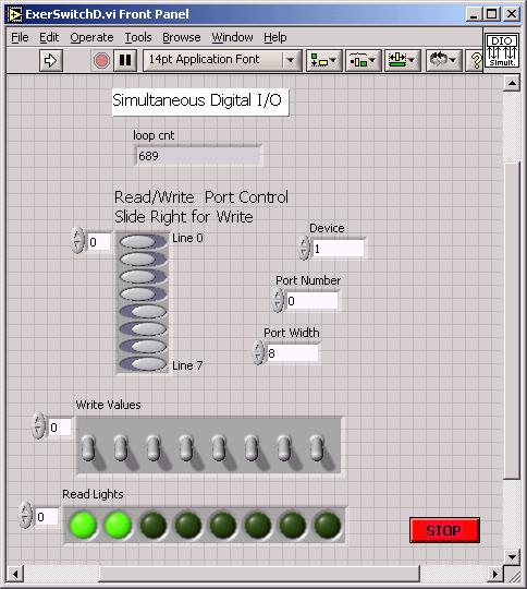
The sets of switches and lights are formed from arrays the controls menu
of the front panel provides. Fill in the arrays with Boolean controls or indicators
of your choice. Think of the 4 switches on the right as D4 through D7 and the
4 lights on the left as L0 to L3. Note use of a STOP button to terminate a run.
You may want to establish these arrays on the front panel
before proceeding with the block diagram, since other actions on the block diagram
(bellow) will use the arrays as input and output.
Do
not attempt to run your digital I/O VI without first setting Device = 1 and
Port Width = 8; otherwise LabVIEW may become hung up in an error message that
will require you to kill LabVIEW from the windows task manager; an especially
painful action if you haven't saved your work...
(2) Design and construct the
block diagram of your exercise VI. See below:
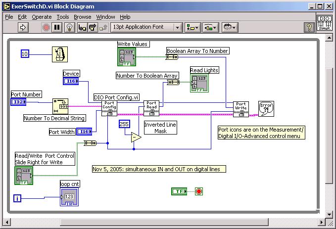
The Port Config, Read and Write icons come from \Measurements\Digital I/O\Advanced
menu. Other icons are labeled for your convenience.
Make sure to enter "0" for the port number. The
"255" on the Inverted Mask Line represents 1111 1111 base 2 = FF base
16. If you enter 254, for example, the bottom bit 0 will no longer read...
Other tips: look in the Dialog menu for error bubble;
pull down right-click menu on a control in the block diagram and un-check
"view as icon" to see control in same format as above.
(3) To test your "exercise"
VI, declare with slide switches that bits 0-3 be READ and 4-7 be WRITE. Connect
on a LabVIEW green block
DI/O 0 to DI/O 4
DI/O 1 to DI/O 5
DI/O 2 to DI/O 6
DI/O 3 to DI/O 7
When you run the VI we will see the 4 left-side READ lights be controlled by
the 4 right-side WRITE switches. Pressing the STOP button will halt your VI.
(4) Now find a green connector
card CB-68LP already hooked up to a MSP-FET 120 board.
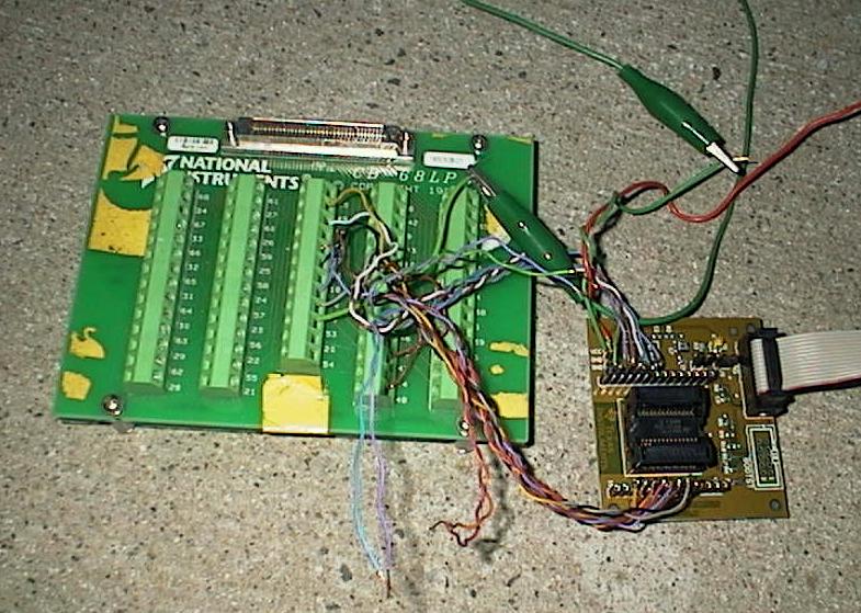
See pinout of the F1232 below (in some cases you may use the F123 board, same pinout,
different A-D method...)
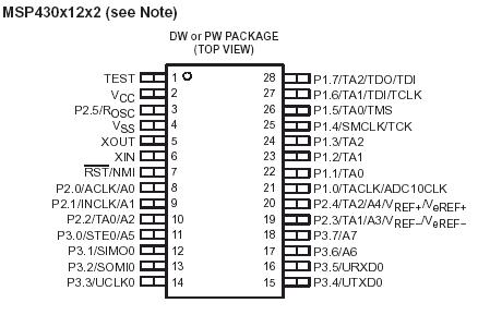
You may want to make sure you see the following connections of LabVIEW to MSP430:
D0 screw 52 to MSP430 pin 21 (P1.0) port 1/bit 0 is the LEFT
motor direc control
D1 screw 17 to MSP430 pin 22 (P1.1) OUT: direc control for
Right stepping motor
D2 screw 49 to MSP430 pin 17 (P3.6) output to inhibit motor,
Left
D3 screw 47 to MSP430 pin 18 (P3.7) " Right
D4 screw 19 to MSP430 pin 24 (P1.3) IN signal from lever switch
on rover, Left
D5 screw 51 to MSP430 pin 23 (P1.2) " Right
lever switch
D6 screw 16 to MSP430 pin 11 (P3.0) IN signal from V-switch
to start movement sequence
D7 screw 48 to MSP430 pin 12 (P3.1)
(future wireless input) back up command
Green GND wire of MSP430 board to pin 53 (GND) of the LabVIEW
connector card.
(P1.4-7 on
the demo board are not available
to the user)
Connect the CB-68LP to the
6024E cable. Make sure the MSP-FET 120 board is connected to its cable
coming from the computer printer port. If the default Lab4Pre06.c "rebuilt"
source code is already in the F123X chip on the board, then the following will
be true:
1. The code
will run an infinite loop [while(1)] that
is continually waiting for D6 (start) to be toggled back and forth. In that
WAIT FOR START state the 4 indicator lights on the left of the front panel are
dark.
The left-most
lights, L0 and L1, represent the directions of the left and right motors respectively,
with both ON meaning forward, (if the L2 and L3 lights are also ON, representing
ON-OFF on the motor controls).
2. After the
START signal is received, all 4 lights will come on (green) and cannot be influenced
for the next 3 seconds. L2 and L3 ON means both motors are uninhibited.
3. If no other
switches are flipped, the code will run about 25 seconds, and between 15 to
20 seconds one of the lights L2, L3 will go out. After 25 seconds all lights
will go out again while the code waits for another START flick.
4.
If after 3 seconds ON the "left" switch (D4) is flicked ON and OFF
you will see the second green light go off for 1 sec; if the "right"
switch (D5) is flicked the first green light will go off for 1 second.
5. If both D4 and D5 are turned ON, the "back up" signal (both L0
and L1 OFF) will be seen until D4 and D5 are off.
6. if D6 is flicked a second time before the 25 seconds are up, then the motors
will be inhibited (both L2 and L3 off) until the cycle is over.
IF you do not see the default
code already at work in the MSP-LabVIEW combination, then you need to download
compiled default code to the demo board:
The source code is Lab4Pre06.c
and is in a read-only file in the EN123 IP folder. Copy and rename the C code
in your own IP folder. Start up IAR Workbench 4. (desktop icon with green screwdriver
crossed with wrench) (2006) ONLY THE FOUR LABVIEW COMPUTERS IN 095 AND THE NORTH
COMPUTER IN 222A HAVE REV 4.0 OF THE IAR SOFTWARE WE WANT.
1. Start IAR Workbench 4.
(2006: only on the 4 machines in 095)
2. Under File menu (or otherwise)
create a new workspace. Don't try to name it yet!
3. From the Project menu create
a project in the workspace. Name and save the project in your IP folder. Add
the renamed MyLab4Pre06.c to the project, MyLab4.
4. With the name of the project
highlighted, go to the Options part of the Project menu. Under the General category
pick the particular MSP microcomputer in your board, likely MSP430F1232 or MSP430F123.
Under the Debugger category of Options look at the Driver window and select
FET Debugger. Hit OK.
5. Now is a time to save the
workspace, with yet another name, in your IP folder.
6. Click on the MyLab4Pre06.c
link and see the code. For now just hit Rebuild All under the Project menu,
and see 0 Errors (maybe several warnings, all about unused variable names...)
7. Now under the Project menu
click on Debug. If all is well with the computer, the cable, the board, the
chip and the project options, you should see messages flash by that say "Erasing
Main Memory" and "Downloading Application" if the download is
successful.
8. IAR now puts you in the
debugger. If you are sure about your code, you can just hit Go then Stop Debugging,
and the microcomputer will be left in its infinite loop, waiting for a start
signal. If you are downloading the default code, you should now see button-press
features described above, in red.
So far, so good.
If you had problems downloading,
make sure the cable from the printer port is connected to the JTAG connector,
and that a MSP430F1232 chip is in the socket, properly oriented with
the dimple at pin 1. Otherwise, call for help from JD.
Now your final challenge for Lab4Pre:
Conventions: D6 represents the V-switch on the back of the rover, and flipping
it to its center position is the start signal. Let D4, D5 represent proximity
switches for the front left and right sides of rover; Let L0 and L1 represent
the directions of the wheels left and right. Both lights ON means rover going
forward. For now, let L2 and L3 ON represent signals to uninhibit the
left and right motors respectively. (Inhibit means the motor stops and
"relaxes": offers no resistance to turning).
Modify your version of the default code so that when a left or right wall
is detected (after being on for 3 seconds) the rover
1. Stops for one second (4 cycles)
2. Backs up for one second
3. Stops for another second
4. Turns to the center
(CW for left, CCW for right wall) for 3 cycles (each cycle is about 250 msec:
100 cycles for 25 seconds...)
5. Stops again for one second
6. Goes Forward until it hits another wall or time is up or (see below) D7 in
switched ON.
Also, arrange that switch D7 turned ON causes the rover to
1. Stop one second
2. Go backwards until the D7 is turned OFF.
If D7 is OFF then the rover will not go backwards.
See suggested code below:
tstP3 = P3IN; //
read port 3 and call it tstp3, a local variable
tstP3 &= 0x02; // mask out all but p 3.1, D7
while (tstP3 == 0x02) // where D7 is sent to pin 12 on
the MSP430 chip
{
your backup code goes here...including some form of
the line below...
P1OUT = mask_op(P1OUT, mask_zone, 0x00);
// also, inside the while loop keep checking on backup status by repeating
tstP3 = P3IN;
tstP3 &= 0x02;
}
Possible FTQ:
Explain how the C assignment statement works.
Explain how a While loop in C works.
Explain what base 16 notation is in the C language, and what the hex letter
C is in base 10.
Free Advice: See Quickie C file for understanding
of some default code. Consider describing your problem as a series of STATE
changes: Forward to Inhibit to Reverse to Inhibit to Turn to Inhibit to Forward.
Study the default code and its comments for what and how the C instructions
work. Attend to assignment statement format, and if statement structure.
Consult the yellow IAR User Guide for information about the features of the
debugger, including single-stepping through code.
12 points; 1 point bonus if all specs are met the first
time you demo.