Lab
4PreDIO: LabVIEW Digital I/O as prelude to
Embedded Code Simulation of Robot Rover
(Simultaneous
Digital Read and Write, and Arrays, in LabVIEW "exercise" program)
Background: Here
you will become acquainted with the digital I/O of LabVIEW, then use a VI you
create to exercise embedded C code that will run your mechanical rover for lab
4Pre. You'll start with a VI derived from National Instruments sample code;
the code reads and writes from 8 digital lines "simultaneously." You
will create an "exercise program" for an embedded microprocessor board.
Requirements:
(1) Lay out a front panel for
your exercise VI: See template below:
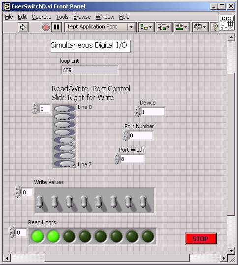
The sets of switches and lights are formed from arrays the controls menu
of the front panel provides. Fill in the arrays with Boolean controls or indicators
of your choice. Think of the 4 switches on the right as D4 through D7 and the
4 lights on the left as L0 to L3. Note use of a STOP button to terminate a run.
You may want to establish these arrays on the front panel
before proceeding with the block diagram, since other actions on the block diagram
(bellow) will use the arrays as input and output.
Do
not attempt to run your digital I/O VI without first setting Device = 1 and
Port Width = 8; otherwise LabVIEW may become hung up in an error message that
will require you to kill LabVIEW from the windows task manager; an especially
painful action if you haven't saved your work...
(2) Design and construct the
block diagram of your exercise VI. See below:
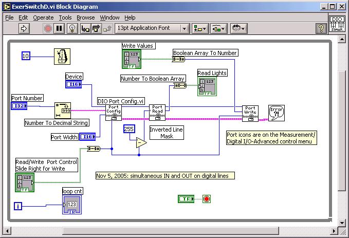
The Port Config, Read and Write icons come from \Measurements\Digital I/O\Advanced
menu. Other icons are labeled for your convenience.
Make sure to enter "0" for the port number. The
"255" on the Inverted Mask Line represents 1111 1111 base 2 = FF base
16. If you enter 254, for example, the bottom bit 0 will no longer read...
Other tips: look in the Dialog menu for error bubble;
pull down right-click menu on a control in the block diagram and un-check
"view as icon" to see control in same format as above.
(3) To test your "exercise"
VI, declare with slide switches that bits 0-3 be READ and 4-7 be WRITE. Connect
on a LabVIEW green block--
DI/O 0 to DI/O 4
DI/O 1 to DI/O 5
DI/O 2 to DI/O 6
DI/O 3 to DI/O 7
When you run the VI we will see the 4 left-side READ lights be controlled by
the 4 right-side WRITE switches. Pressing the STOP button will halt your VI.
Next proceed to the Lab4Pre
Arduino "pde" C coding challenge.