Lab
4PreDIO: LabVIEW Digital I/O as prelude to
Embedded Code Simulation of Robot Rover
(Simultaneous
Digital Read and Write, and Arrays, in LabVIEW "exercise" program)
Background: In
Labs 0 and 0.5 you became acquainted with Analog OUT and Analog IN via LabVIEW.
Here you will become acquainted
with the digital I/O of LabVIEW. You will use a VI you create to exercise embedded
(Arduino) C code that will run your simulated mechanical rover for lab 4Pre.
What we want here are 4 front "Boolean" panel switches and 4 front
panel digital indicator lights that will simulate sensory input and outputs
to motor simulated stepping motor drivers.
(1) Lay out a front panel for
your exercise Lab IV VI that looks something like the template below:
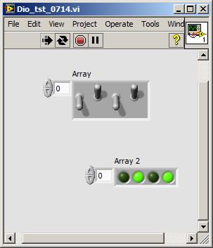
From the controls menu of the front panel window go to the Array... menu and
select the first item, a blank array. Create either a switch or a LED and drag
it into the array to populate it (drag array size...): 4 of each, as shown above.
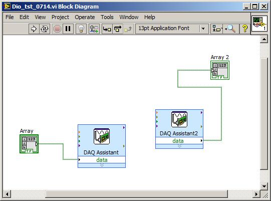
Have the 4 front panel switches
go to a DAQ Assistant that is set for Digital Out, Line,
not Port.
The 4 toggle switches will
be called D4 D5 D6 D7; the green LEDs D0 D1 D2 D3.
Review your Lab 0 notes, namely:
To find the DAQ Assistant icon go the the block diagram Functions Menu--at the
top of the bottom see Measurement I/O: slide off onto NI-DAQmx;
on that menu look for DAQ Assistant (lower left
area). Once you get that icon on your block diagram and click on it up will
come a window that asks: Acquire or Generate signals? Choose Generate.
Choose Digital Output. Click on Digital Output
and choose Line Output. Up will come a window showing
tab Physical. At the top of the white space it
should say Dev1 (PCI-6024E). Choose
ports 4-7 then click Finish. Now you're back to
the first DAQ Assist screen. Should you click on 1 Sample On Demand? At
the bottom right click on OK. LabVIEW will
crank through several seconds of "Building VI." Now you're ready to
wire your array from the front panel to the DAQ Asst so the switches will alter
various pins (19, 51, etc) on your green connector card.
The 4 switches are D4 through D7 and the 4 lights are D0 to D3.
These elements can be either
inside a while loop or you can run the VI continuously...
(2) To
test your "exercise" VI connect on your LabVIEW green block--
DI/O 0 to DI/O 4
DI/O 1 to DI/O 5
DI/O 2 to DI/O 6
DI/O 3 to DI/O 7
When you (continuously) run the VI we will see the 4 READ lights controlled
by the 4 WRITE switches. Pressing a STOP button will halt your VI.
Next proceed to the Lab4Pre
Arduino "ino" C coding challenge.