Lab 4Pre: Arduino embedded coding
(continued from successful LabVIEW DIO VI)

Here you will simulate control of a robot rover using a Atmel 328 microprocessor communicating with LabVIEW controls and indicators; the code is created in the Arduino environment. Read about Arduino at www.arduino.cc. Arduino software will "compile" a version of C as a *.pde file, not a *.c file.
Later you'll see that in "Setup" code Arduino declares its variables. In "loop" Arduino runs an infinite while loop...inside of which Lab4Pre default code and your modification of it goes.
Arduino does not have a single-step debug feature. You can debug your code with the "serial monitor" that will print out in a "serial window" values of variables you call for. In what you have as default code is a for loop that runs 100 times and has a 250msec delay in each loop, and a printout of variables at the end of the loop.
Find a LabVIEW green connector CB-68LP with wires running to a STD socket plugged onto a DE-11 card on which a white breadboard has blue Arduino card mounted, and the Arduino card hosts one end of a USB A-B cable going into a USB port of your computer. The LabVIEW connector will have a 68-pin cable running to the 6024E card, as usual...
In the current EN123 IP folder you will find folder Lab4Pre11 inside of which is Arduino "sketch" Lab4Pre11.pde.
Start running the Arduino software rev 22 (desktop icon of infinity sign in teal).
Under File/Open bring up Lab4Pre11.pde (read-only) and immediately rename it to be in your IP folder, and take off the read-only restriction.
Under Tools select the Arduino card on your board: Duemilanove or Uno; select the USB port number (you may have to check with Device Manager...)
Make sure the default code compiles: click on the left side arrow "verify" and wait for mssg "Done Compiling" with no red text... below is the first lines of the Arduino default code.
Comments in code tell you which Arduino pins are associated with what rover signals.
The next section of default code shows void setup( )

as the way Arduino assigns input and output status to variables declared above.
The robot rovers which LabVIEW simulates the inputs and outputs of have the following conventions:
V-switch is OFF when LO and ON when HI;
When an INHIBIT pin 4 or 5 is LO the motors are UNINHIBITED. Arrange that the two lights on the LabVIEW simulation which represent motors ON or OFF ... that those lights are OFF when the motors are ON (the motor drivers on the rover turn on when at logical LO state).
For now, the lever switches on the simulated bumpers are normally LO but go HI when contacting a wall. (on the rovers themselves this convention is reversed: when a lever switch hits a wall it sends a GND signal to the computer...)
loop( ) is an infinite while loop in Arduino, and inside is loop() is a for loop on pp to pp_max:

notice that there is a 3 second wait before the code accepts bumper lever input: ( pp > 12 ).
The test on pin 3 is for your "backup mode" described below.
The last section of default codes ends with an interrupt to respond to the V-switch.

This section of code shows the serial.print of pp and (for 4Lam) the phototransistor inputs.

1. The code will run an infinite loop that is continually waiting for virtual switch D6 to be flipped up to start the pp loop. In that WAIT FOR START state the 4 indicator lights on the left of the front panel are LOW.

The left-most lights, L0 and L1, represent the directions of the left and right motors respectively, with both ON meaning forward, (if the L2 and L3 lights are also ON, they represent that the motors themselves are ON).

2. After the START signal is received, all 4 lights will come on (green) and cannot be influenced for the next 3 seconds.

3. If no other switches are flipped, the code will run 25 seconds, After 25 seconds all lights will go out again while the code waits for another START flick. Serial.print will show the pp count.

4. If after 3 seconds ON the "left" switch (D4) is flicked ON and OFF you will see the second green light go off for 1 sec; if the "right" switch (D5) is flicked the first green light will go off for 1 second.

5. if D6 is turned off before the 25 seconds are up, then the motors will be inhibited (both L2 and L3 off) until the counting will stop.

Now your final challenge for Lab4Pre:
To repeat: D6 represents the V-switch on the back of the rover, and flipping it to its center position is the start signal. Let D4, D5 represent proximity switches for the front left and right sides of rover; Let L0 and L1 represent the directions of the wheels left and right. Both lights ON means rover going forward. For now, let L2 and L3 ON represent signals to uninhibit the left and right motors respectively. (Inhibit means the motor stops and "relaxes": offers no resistance to turning).

Modify your version of the default code so that when a left or right wall is detected (after rover being on for 3 seconds) the rover
1. Stops for one second
2. Backs up for one second
3. Stops for another second
4. Turns to the center then stops for one second
(CW for left, CCW for right wall) for one second
5. Stops again for one second
6. Goes Forward until it hits another wall or time is up or (see below) D7 in switched ON.
thus we will see 4 stops during the turn maneuver

Also, arrange that switch D7 turned ON causes the rover to
1. Stop for 2 seconds (motors inhibited)
2. Go backwards until the D7 is turned OFF.

If D7 is OFF then the rover will not go backwards (unless it hits a wall).

Possible FTQ:
Explain how an interrupt works.

Free Advice: re-compile ("verify") frequently so you don't have too many keystrokes to consider if an error pops up in compling...

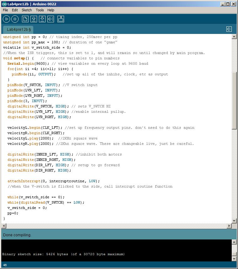
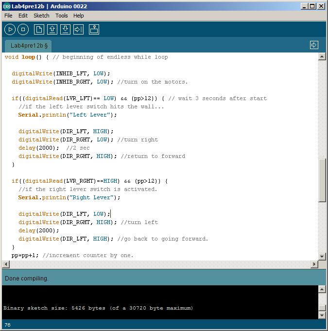
See Quickie C file for understanding of some default code. Consider describing your problem as a series of STATE changes: Forward to Inhibit to Reverse to Inhibit to Turn to Inhibit to Forward. Study the default code and its comments for what and how the C instructions work. Attend to assignment statement format, and if statement structure.

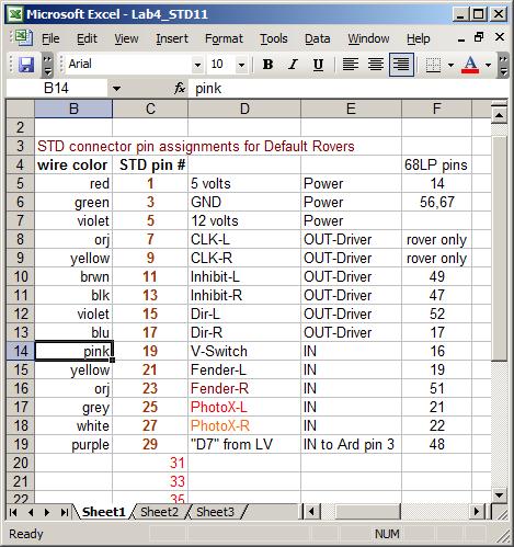
The STD blue socket pinout:

Arduino Uno top view:

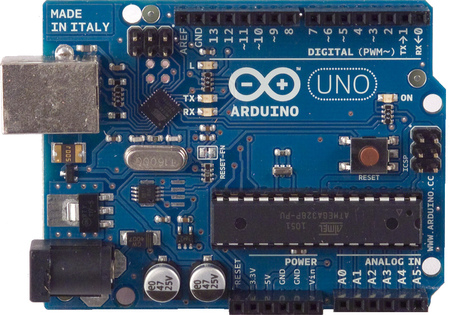
Note the Analog-in pins at the bottom left...