Lab 4: Ballistic Guidance of RC Car by LabVIEW
Background: Here you become acquainted with LabVIEW digital out and using arrays to index a for loop. Another theme: wireless transmission, useful for various telemetry situations.
In this lab, the RC car will be guided ballistically by computer: no feedback used here.
There will be a demo in class of the Mayhem RC car capabilities, including how it turns (opposite rotation of left and right wheels) and how it can slide left or right by tilting all 4 wheels at once.
The disassembled transmitter
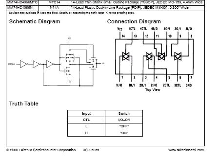
will be hooked up to wires from 4066 switches which in turn are controlled by
digital out's from the green LabVIEW connector board. The power supply must
be set to 10 volts for the transmitter and 5 volts for the 4066 card.
Requirements:
(0) You should do Lab 4 in room 222A, on the RC Car track there. Already set
up at each computer table is a transmitter controlled by 6 digital outs from
LabVIEW. Use the MAX utility to verify what each digital line (0-5) does for
car control. And Analog CH1 is connected to the Scoreboard start switch.
Don't forget to put a charged
9.6v battery in your car on the track. Make sure you are using a transmitter
on the same frequency as your car's receiver. (27, 49MHz). Notice how the digital
outs control 4066 quad analog switch chips.
Go to http://www.fairchildsemi.com/pf/MM/MM74HC4066.html
to see the datasheet of the 4066.
(1) As a preliminary exercise
for Lab 4, you will want to create an array, have it be an input to a FOR loop,
have delay (200 msec?)in the loop, and thereby produce a digital out waveform.
Such waveforms will be needed to control translation, rotation and tilt of Mayhem.
(2) Place your vehicle behind the duct taped border at one end of the track, and a block of wood under the halogen light at the other end of the track. (Halogen lights are off for this experiment.) You may want to be careful about the orientation ("initial condition") of your vehicle. Between your car and the goal block will be a big plastic tub. We may place the tub plus or minus 6 inches from the center of the track.
Your goal will be to create
a LabVIEW VI that will drive your car around the tub and strike the wooden goal
so the laser beam aiming at a PN150 is exposed. When this happens you will score
5 points on the automatic scoring system. Your car must knock over the goal
block in less than 32 seconds. AUTO-start: Your car should not start moving
until a signal (purple wire to A-in-CH1) from the scoreboard is switched ON.
The switch starts the timer.
Below is closeup of a transmitter
with its control pads exposed:
 For translation,
rotation and tilt there are control pulses generated by a chip on the xmitter: the
solder pad sources of these signals are labeled above: translation is to the left,
rotation to the right. The large pads at the top are for tilt. The pulse pads connect
to subsets of the "instruction pads", of which there are 4 strips each.
For translation,
rotation and tilt there are control pulses generated by a chip on the xmitter: the
solder pad sources of these signals are labeled above: translation is to the left,
rotation to the right. The large pads at the top are for tilt. The pulse pads connect
to subsets of the "instruction pads", of which there are 4 strips each.
(3) For no FTQ, have your car
knock over the goal block on its very first try. Or demonstrate the use of digital
channel 6 as an input for the starter signal.
In your team's demonstration test of Lab 4 you have 3 chances to knock over the goal; if you fail 3 times in a row, try again the next day.
Free Advice: If an array of switches is sent into a for loop then the number of elements in the array will determine the iteration cycles of the loop. As you did in Lab 0.5, create a while loop to wait for the starter switch to be flipped. From MAX you will have seen that OFF is about 0v and ON is about 1-2 volts.
You may want to begin and end your VI by sending pattern 0 to Digital Port Out.
The control points need special pulse signals generated on the transmitter card "encoding" section. The 4066 quad analog switch chip direct where the pulse trains go to the various "pads" on the controller. If 4066 switches don't seem to turn off or on reliably then you should run 1-5K Ohm resistors from the translation and rotation pads to ground (on the breadboard). Such resistors to ground will "pull down" or load the signal so it will not be susceptible to leakage from the pulse inputs.
You may want to pay careful attention to the track surface at the time of testing: how much dust or grit is on the surface, etc. for repeatable performance. We may run the floor cleaning robot Broomba over the surface to remove fluff.