Lab
5: Thermistors sensing temperatures
Background: All
resistivity (ρ) is temperature dependent, which is usually not good, unless
you want to sense temperature, then you want to use materials that change resistance
rapidly (in magnitude and time) as temperature changes. Such is the case with
thermistors. Remember from materials science or electricity class how metals
and nonmetals differ in the slope of their resistance-temperature characteristics...
At any rate, from the POV
of EN123, thermistors (unlike say mercury bulb or liquid crystals) can be involved
in converting temperature directly to voltage (use voltage divider).
Requirements:
(1) Design and build an electronic temperature sensor, starting with two NTC
(negative-temperature-coefficient) thermistors. You will want the thermistors
to be part of a circuit that generates a temperature-sensitive voltage. In addition
to connecting with your voltmeter, your temperature sensor output should feed
into LabVIEW, to be displayed as a chart waveform. Use math functions in LabVIEW
to convert from voltage to temperature.
From various thermistors in
stock and around the lab, choose what resistance you would like for the tests
below. 1K Ω would be a default choice.
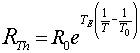
Knowing the equation
measure the series resistance of your two thermistors, as you aim a heat
gun or hair dryer at the the pair to provide a T0 (near 50 deg C, measured with
Fluke 52) for the equation. The series resistance/2 will be R0. Then pick a
second temperature and record a second resistance, so you can calculate TE.
If all went well the reading from a third temperature should agree with the
Rth you calculate.
For the mechanical arrangement
of your thermistors, it will be best if you use a 4-screw-terminal block to
connect the leads of the thermistors to the wires leading to a Wheatstone bridge.
Use a Fluke 52-II-series
thermocouple-based temperature sensor to calibrate your temperature sensing
circuit. The Fluke 50 will be used as the standard for the temperature tests
described below.
You may also want to calibrate
your own epithelial biosensor, at the tip of your index finger.
(2) In the first test
variable temperature warm air will be supplied by a Steinel 1600-series heat
gun. The nozzle of the heat gun will be extended by sheet metal (flashing)
held in tube form by 3 hose clamps. You should fix the heat gun in a vise and
aim the stream at your thermistor-pair, held by a clamp, and the thermocouple,
independently held by a clip or another clamp. Your thermistors should be in
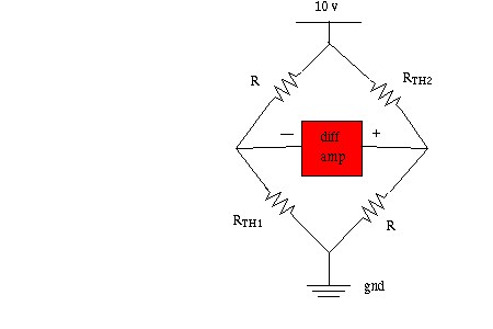
opposite arms of a Wheatstone bridge, to linearize the Voltage-out response.
Calibrate, (with the help of your calculated TE). All you will care about for
this test is the temperature range 40 to 60 deg C.
Do not turn up the heat
gun above 90 deg C or so... it is capable of heating up to 1100 deg and becoming
a bio-safety hazard.
For your test
we are allowed to move the heat gun ±1
inch from your thermocouple calibration point, along the axis of the extension
tube. We will hide the heat gun temperature control in a sleeve. The test temperature
will be between 40 and 60 deg C. You are not allowed to put tape on the thermocouple.
Instead, use clamps or clips to position the thermocouple near your thermistors.
A Post-It will cover the display of the Fluke meter until you write down your
estimate.
Once you say
you're ready, a 60 sec interval will start. We will switch the Fluke to MAX
mode: During the 60 seconds we are allowed to adjust the temperature control
knob under the sleeve... At the end of the 60 seconds we will press the HOLD
button, which will lock into the hidden display the maximum temperature of the
past 60 seconds.
Your challenge: Estimate what
the max-temperature reading was, based on the output of your thermistor circuit
(and perhaps placing your "neural-network-trained" index finger near
the thermocouple...) After we write down your estimate on the Post-It, we'll
uncover the display and see what the correct=thermocouple answer is. Your estimate
must be within ± 1.3°C of the Fluke for you to proceed to the next
test; if you miss, come back the next day for another try...
(3) In the second test you
will place the Fluke probe + thermistors in stirred chilled tap water.
A few shakes of salt may be added to the water!
We will guarantee that the chilled water temperature reading will be in the
range 5 to 15 deg C.
As before, the Fluke display
will be covered and we'll announce a 60 second interval during which the Fluke
will be in the Record MIN mode. At the end of the 60 sec we will press the HOLD
key and lock in the answer.
You should have your thermistors
(and perhaps your finger) in the chilled water during this interval, and be
monitoring your circuit's output. Again you are to make a estimate: What was
the minimum water temperature during the 60 sec interval? The position
of your thermistors in the stirred water won't be critical, except perhaps for
depth below surface.
At any rate, your estimate
must be within ± 1.0°C of the Fluke for you to meet requirements.
(4)
We may observe that for the 60 second intervals of the 2 tests you produce a
LabVIEW waveform with temperature as a function of time.
If
either of your temperature estimates is out of range, you need to come back
a day later to try again. If you are correct on both temperature estimates
ON THE FIRST TRY then there is no FTQ and a 2 bonus points.
What
resistance thermistor should you choose?
Lower resistance thermistors may be susceptible to self heating, and higher
resistance thermistors may be compromised by parallel conductance from ions
in the cool salty tap water.
Free Advice: Read the lectures notes on temperature sensors on the EN123
website.
And look at the 2001 archive
site Lab 2 writeup for old advice on how to construct your thermistor-system...
Below is a suggestion for
arranging two NTC thermistors. The "R" resistors should be about the
same magnitude as Rth, so the differential voltage will be near zero at mid-range.
The 10v "excitation voltage" should really be somewhere around 1v
to 6v, to minimize self-heating; Use the "6v max" on the Agilent E3631A
power supply in the lab.
You may want to have one mode of your circuit specialized for great sensitivity
over the 5-15 deg range, and another mode for sensitivity in the 40-70 deg range.
You can measure the differential voltage directly with your DMM on DC volts.
If the reading seems to fluctuate too much, consider placing a 30 micro-Farad
capacitor across the left and right sides of the bridge...
Neither side of the bridge above is "ground";
ground (or reference) of the power supply for Vex = 10 should be sent to AGND
of LabVIEW, and the two sides of the bridge read separately and subtracted (or
be in "differential mode" from MAX properties menu).
Beware that the temperature
in the heat gun air stream may vary by several degrees over a few millimeters
distance!
Possible FTQs for Thermistor Lab:
You may be asked a question based on the lecture notes discussion of self-heating
in thermistors. Likely we will show you the Simulink simulation mentioned
in the notes, and ask you to predict something about ΔT or Vout from the
circuit in the class demo, based on changes in the thermal properties of the
thermistor, or the size or shape of the thermistor.
OR
Explain extemporaneously, perhaps with the aid of a diagram, the difference
between diffusion and mobility of electrons with regard to the how a thermocouple
works.
Bonus scoring: 1 point bonus for right-the-first-time
on hot air; another bonus point for right-the-first-time on cold water; a third
bonus point if you're right first time on both.