Lab
7: Vibration analysis with strain gauges
Background: You
encountered stress-strain curves in your materials course, and here you will use
strain gauges to measure the vibration frequency of a rigid body clamped at one
end. In a perfect world we would use long bones, such as sheep femurs, to study
the use of strain gauges, but to simplify the attachment of the strain gauges we
will study rigid bars--aluminum, brass, fiberglass, etc.
Fiberglass, being a composite
material, is closest in properties to bone. You will look at transient bending responses
of the materials with 54622A digitizing scope. The Math/FFT feature of the 54622A
will be able to show you the spectrum of the waveform.
You will need to use the trigger
feature of the scope to capture the vibration transient.
LabVIEW will also acquire the waveform, and try to analyze it for you.
Requirements:
Find a bar with strain gauges glued to it. Look in a box on top of the 095 refrigerator.
(1) Measure the resistances of the SGs, and make sure they're either 120 or 350
ohms. If you bend the bar slightly by hand, the resistances should change slightly
too.
(2) Arrange the SGs into a Wheatstone bridge, and have the outputs of the bridge
go to the + and - inputs of a 524, set for gain of 100 or 1000. Make sure the SGs
are in the bridge to optimize response for bending.
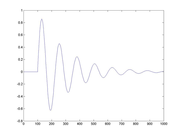
(3) Clamp your rod in a vise, paying attention to the length of the rod free to
vibrate. Observe on the scope a decaying oscillation when you "ring" the
bar by striking it on the end. Understand triggering on the 52622A scope enough
that you can capture as a single trace one of the transient oscillation bursts due
to flexing of the of your rod. Record the frequency of oscillation, and the time
constant of decay of the burst. See Matlab-generated figure below.
How do the frequency and time constant change if you shorten the length of rod free
to vibrate? (What is the formula for the oscillation period
of a pendulum? Use dimensional analysis.)
(4) As you did in Lab 6, invoke the Math/FFT feature of the 54622A scope to look
at the spectrum of your single waveform. Does the spectrum tell you the fundamental
frequency of oscillation? Does the spectrum result agree with the time base measurement
of of oscillation frequency?
(5) By reviewing the website
lecture notes on Strain Gauges, calculate (estimate) the peak stress in
the material. You may find the modulus of elasticity at
http://ourworld.compuserve.com/homepages/MJVanVoorhis/t000.htm
or with the help of Google. Yes, you are dealing with a bending moment, and
there is a torque (Fxr) but estimate the force involved as best
you can.
Your main calculation problem:
what is the relationship between amplifier output and stress? Attend to the
related Strain Gauge Quiz clues for more detail...
(6) Temperature effects: try heating
with a hair dryer the rod stock near one of your strain gauges. Do you detect any
change from the unloaded strain gauge amplifier DC output? How should heat affect
the strain gauge, mechanically?
(7) Send the output of the instrumentation
amp to an analog input channel of LabVIEW, and thence through LabVIEW's FFT Power
Spectrum analyzer, as you did in Lab 6: Do you see the same spectrum in LabVIEW
that you saw on the 54622A? What is a good sampling rate for the vibration frequency?
(8) Establish a trigger
in your LabVIEW VI: Arrange that after you start your VI it waits until a threshold
is exceeded in the input waveform before starting to acquire one second worth
of vibration. Remember what you did in Lab 0.5, to have one process trigger
another. Try to build your trigger system with a SEQUENCE: in one of the sequence
frames wait for the trigger event, in the other frame complete the spectrum.
Possible FTQ: What happens if a strain gauge and fixed resistor in your
Wheatstone bridge are swapped?
Free Advice: Read the lectures notes on strain gauges from the
EN123 archive website.
Make it so: that the unloaded amplifier output is close to zero.
You may want to use the offset pins on the 524 to make sure that at a gain of
1000 the bridge output is less than 10 mV!