Lab 8Thor:
Thor DRV001 micro-stepper motor to probe a pressure-sensitive resistor and then
a blaberus spine
(developed originally as a summer UTRA project by Kelsey Macmillan '11)
Background: You
will have completed Lab 8 and either immediately after or later can try lab
8Thor:
Hardware:
ThorLabs DRV001 ($585) Motorized Linear Actuator
(See detailed product information at: http://www.thorlabs.com/NewGroupPage9.cfm?ObjectGroup_ID=1881)
This device is capable of linear travel of up to 8mm with a "Minimum Incremental
Movement" of 60 nm--that's 0.06 of a micron...
Control signals and power for the actuator occur through a ThorLabs
BSC101 (now 201) controller ($1285)
http://www.thorlabs.com/newgrouppage9.cfm?objectgroup_id=1704
which receives instructions from a Thor software application ("ATP User")
we have running on the Lab 8 computer.
Requirements:
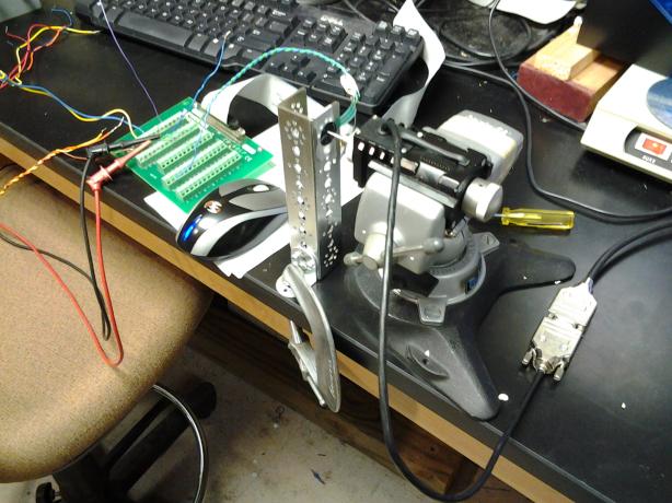
(1) Pressure-sensitive
switch: On the lab bench next to the Lab 8 computer are the DRV001 motor
in a vise and a pressure-sensitive resistor taped to a Tetrix channel held to
the countertop by a C clamp. The probe of the motor is aimed to touch the pressure-sensitive
resistor (PSΩ).
The PSΩ is "open
circuit" until contacted, then its resistance drops in the 10K Ω
range. At LabVIEW Ain 7, from where a 10KΩ resistor to ground forms a
voltage divider, you can see the pressure response in volts.
With the power to the
BSC101 turned off,
rotate the manual control knob at the back of the DRV001, advancing the
probe toward the PSΩ until you see the Ain 7 voltage and the same voltage
from your DMM (digital multimeter) rise up to about 2 volts. Back off.
(2) Turn on the BSC101 controller.
Open APT User and study the screen.
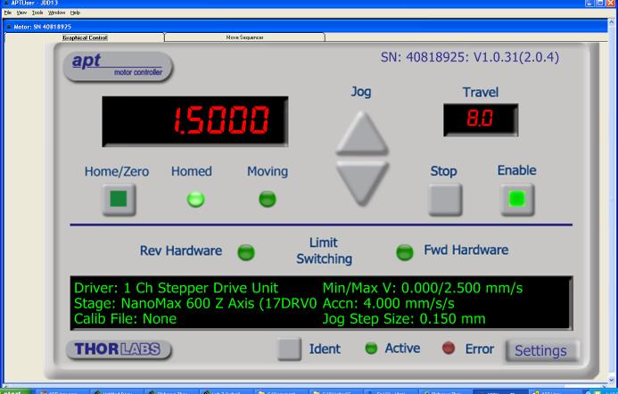
If you press the ^ Jog button a few times the probe should advance enough to
apply pressure to the PSΩ. Back off with the V down Jog button.
Figure out what the Home/Zero
button does.
You are in the "Graphical
Control" mode. Now
click on the next tab over to the right, "Move Sequencer" above the
main window. You should see a blank sequence (or the last user sequence... right-click
to delete all lines if that is the case...). You may want to do some "downsizing"
of the window... you should see "LOAD" in the bottom right of the
window...
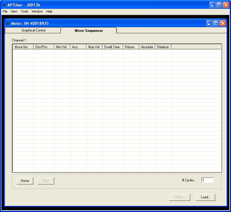
Right-click in the main window and pick New Line. For now choose Absolute move
of say 3.0 (mm). Dwell time (added on after a move) is in msec, so try 1000
for the first dwell time. For max velocity say 2 (for 2mm/sec). Create a second
line with a desired move to 1.0 absolute, with a 500 dwell time, and same velocity.
Go to the bottom right of the screen and save in your IP folder this move sequence.
At the bottom left click
on Run, and look closely at the probe tip; you should see it move out and back
in over the course of a few seconds. Position the probe near the PSΩ and
observe the probe repeatedly generating pressure voltages as it advances and
retreats.
Try adding 6 more lines
to your sequence so the probe and stimulate and relax the PSΩ (or a blaberus
spine).
Back in the Graphical Control Panel,
click on Settings, go to motor driver and the advanced tab. Make sure TRIG OUT
is selected as well as ABSOLUTE (not "relative"...).
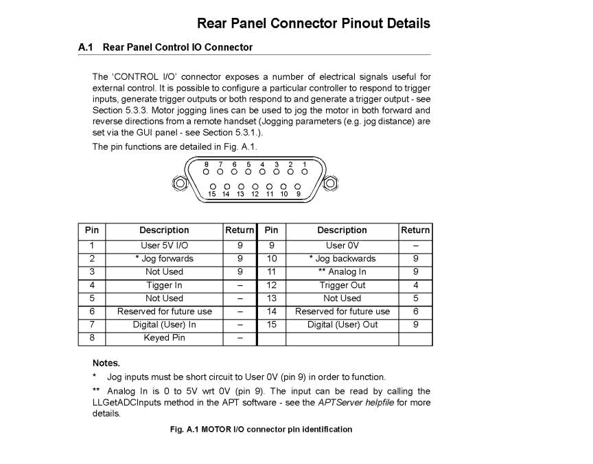
See pinout below for the back connector
of the BSC101. We run a grey wire from pin 12 Trig Out over to the LabVIEW side,
where the grey (and brown ground) wires can be hooked up to a Ain channel for
the 6024E. With voltmeter set across the grey and brown wires click Run again
and notice that Trig Out is 5v when the probe is moving.
(3a) Triggering
LabVIEW to record and display PSΩ
response: Position the DRV001 probe about 1mm in front of the PSΩ.
Create a LabVIEW VI
that records at 1000Hz sample rate for the duration of your move sequence, and
display the Ain ch 7 response of the voltage divider as a function of time on
a front panel waveform graph. You should be able to note speed of the probe
and dwell times.
3(b) Triggering to capture blaberus
AP spike data as the probe moves: Rename your Lab 8 VI and add a while
loop that waits for the Trig Out to go HIGH; when it goes HIGH then have the
next frame collect data for (say) 10 seconds while the probe is moving back
and forth touching a spine. The spine is about a mm in size and can rotate perhaps
60 deg, so you will need to adjust the distance the probe moves to stimulate
blaberus.
In your new VI have the
Matlab Script time-stamp each spike it identifies.
Have JD position the probe
with its micro-fork lance near a spine that drives spike responses the electrodes
will record.
Press Run on the Move Sequencer
screen, cause the probe to move and the spike recording to begin.
Arrange that the collected
spike data time stamps are written to a file that "regular" Matlab
can access.
Have a function convert
the time stamp data in moving-average spike rate data, that can be plotted as
a function of probe position.
Try another set of runs
with a lower speed of probe movement.
Possible
FTQ: Determine by a longer series of back-and-forth
probe moves if it is possible to fatigue or habituate the blaberus responses.
Can the move sequence be started by a TRIG IN signal to back panel of the BSC101?
-------------------- -------------------
Kelsey Macmillan suggestion
below...
Notes: turn on BSC-101 before starting ThorController.vi.
Max speed is 2.5mm/sec
Make sure the USB A-B cable connect BSC-101 to computer USB port