Lab
8T_2011: Using the Thor BSC-101 to control the DRV001 linear actuator and record
spike events simultaneously (Kelsey MacMillan summer 2011 UTRA project)
Background:
In the normal course of events Lab 8T would follow on Lab 8, recording
from blaberus spines. Here in 2011 you will exercise the Thor linear actuator
to move in a pre-programmed back and forth movement. Simulating blaberus, the
spike counter *.vi will count cardiac waveform events. Here two linked LabVIEW
vi's will run simultaneously.
What follows: Details of the hardware and software you will need for Lab 8T_2011.
Hardware:
ThorLabs DVR001 ($700) Motorized Linear Actuator
(See detailed product information at: http://www.thorlabs.com/NewGroupPage9.cfm?ObjectGroup_ID=1881)
This device is capable of linear travel of up to 8mm with a repeatable precision
of < 1 micron. Controls for the actuator occur through a ThorLabs BSC101
controller ($1300) which receives instructions from from a Thor software application
running on the 8T computer and embedded in your default code.
Software in IP folder...
8T_11_default.vi
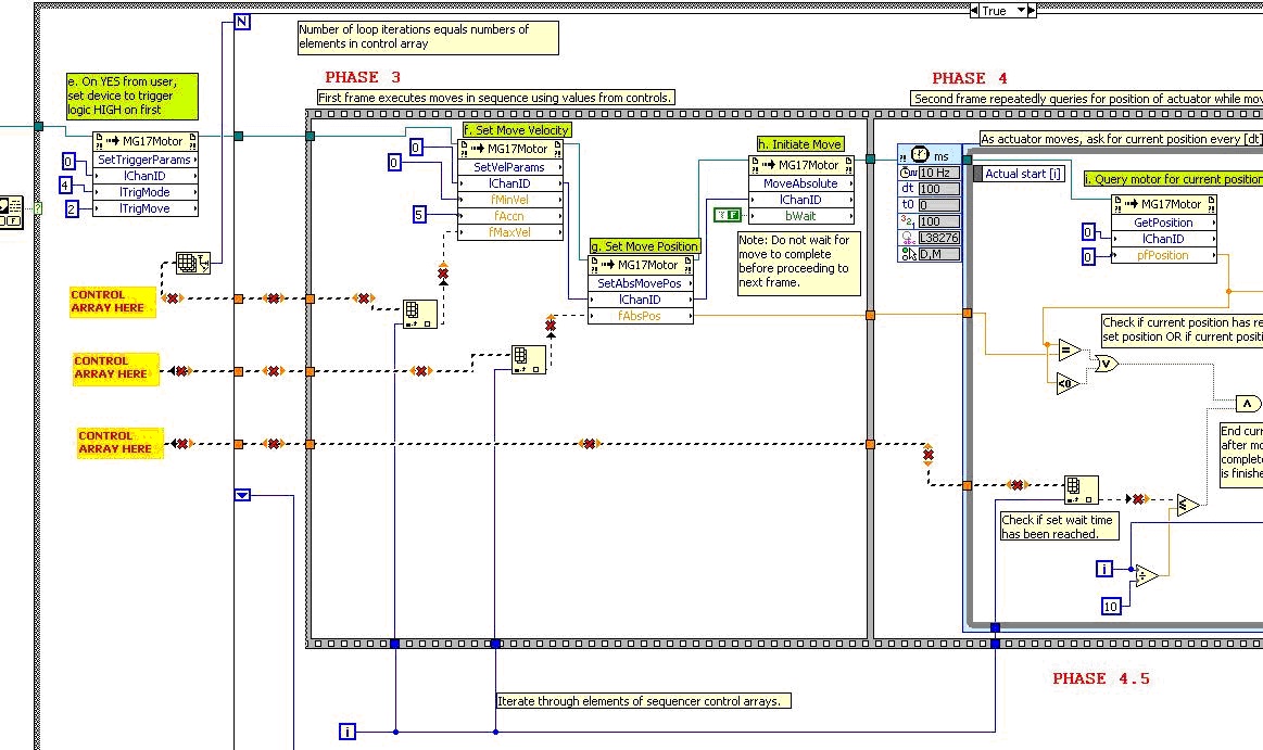
Your LabVIEW virtual instrument will send commands (either sequenced or instantaneous)
to the THORLABS BSC101 controller for the DVR001 linear actuator. All controls
are accomplished by ActiveX controls which appear as "Invoke Nodes"
in LabVIEW. Each ActiveX Invoke Node takes user inputs in the form of numerical
codes and then either "gets" properties from the Thor controller or
"sets" properties of the controller, i.e. sends instructions to the
linear actuator. For specific information on the function of each Invoke Node,
right click the node and consult the Help menu.
Using the VI it is possible to specify
(1) the positions of any number of absolute moves,
(2) the maximum velocity at which the actuator probe should travel, and
(3) the time the device should wait to initiate the next move.
While moves are being completed according to sequencer parameters, the VI program
queries the BSC101 controller for its current position several times per second,
so as to track the position of the actuator in real time. An array of positions
and their corresponding times are saved in a .mat-file over the course of each
program execution. These arrays are loaded as variables in the MATLAB program
complimentary to this VI.
The BSC101 controller can also emit a trigger signal, here to awaken a LabVIEW
VI. During the second phase of the program, the VI instructs the controller
to output a logic HIGH from its trigger I/O pin at the moment when the actuator
begins to execute a sequenced move. This logic HIGH can be read by another device
or VI to set off simultaneous program execution.
Turn on the BSC101 before activating your LabVIEW vi.
Allow a minute or so of "warm up" time. Once you start the VI (and
all is well) the "apt motor controller" will wake up; you jog the
probe in and out. The maximum speed the DRV001 can move with the BSC101 is 2.5mm/sec.
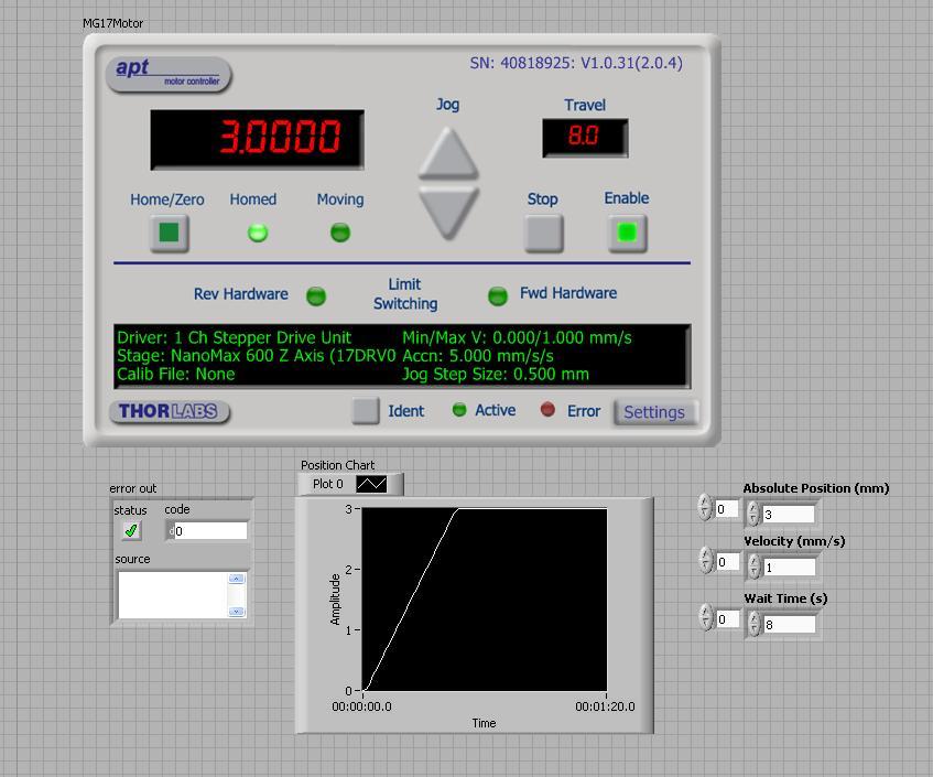
Below is an image of the front panel of the fully functional VI, containing
the Thor manual control interface. The arrays at the bottom right of the front
panel are controls for input position and velocity instructions for the Thor
controller. The Thor panel at the top center of the front panel can be used
to give manual instructions to the Thor controller, and so check functionality.
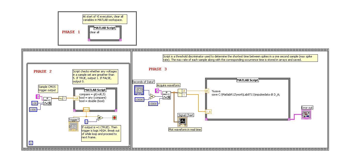
LabVIEW VI (B): 8T_11_PulseRate.vi
This VI (block diagram shows below) is similar to the one used in Lab 8. This
VI differs because it collects data over an extended period of time, then saves
all data to a *.mat file, which can be loaded in a MATLAB m-file. All data analysis
is performed in a MATLAB m-file, rather than in a MATLAB script in the VI. Also
different: the VI, once started, waits in a while loop until it detects a logic
HIGH from the NI board, at which point it breaks out of the loop and proceeds
to collect electrical impulse data. The logic HIGH should originate from the
8T_11_ThorController VI, and indicate that the actuator probe has begun moving.
The period of time over which electrical data is collected is specified by a
control in the VI front panel.
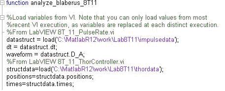
 MATLAB
M-File A: analyze_blaberus_8T11.m
MATLAB
M-File A: analyze_blaberus_8T11.m
All data collected from both VI's is loaded then analyzed in this matlab
script. The code for loading saved .mat files is included below. Specifically,
the data consists of position data for the linear actuator, and electrical impulse
data from the electrodes at the specimen. The rest of code in this file (not
shown) plots both data sets and then uses a threshold discriminator to count
spikes.
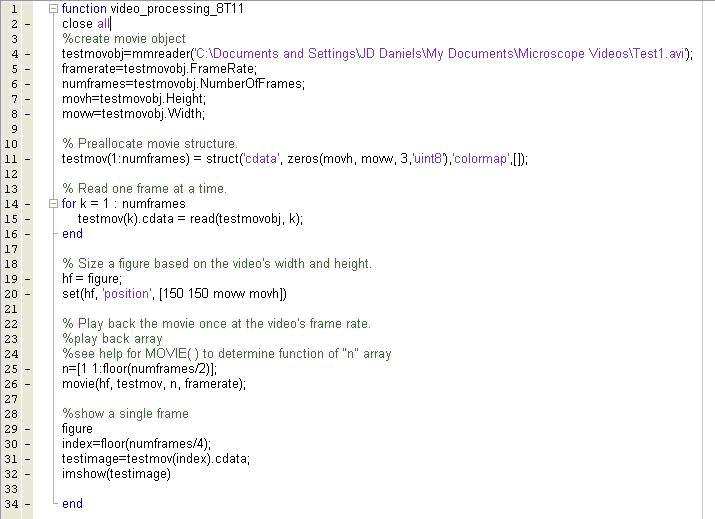
MATLAB M-File B: video_processing_8T11.m
MATLAB's image processing tool box allows images and video to be loaded,
manipulated, analyzed, and played back. This m-file, in the image below, uses
just the basic image processing tools. It loads the file, the plays it back,
and then selects a single frame to display as an image.
0: Complete the default
VI (IP folder) shown below by adding 3 control arrays. To help you out, we've
placed red and yellow signs that indicate where to connect the needed arrays
controls.
Requirements:
Your goal is to assemble
a VI + Thor controller to move the probe on a schedule of
1. Start at 0 and move
to 4 mm out at 1mm/sec;
2. Pause 2 seconds.
3. Move back to 1mm out, at 2mm/sec
4. Pause 2 sec
5. Move out to 8mm at 2.5mm/sec
6. Pause 2 sec
7. Move back to home at x=0.
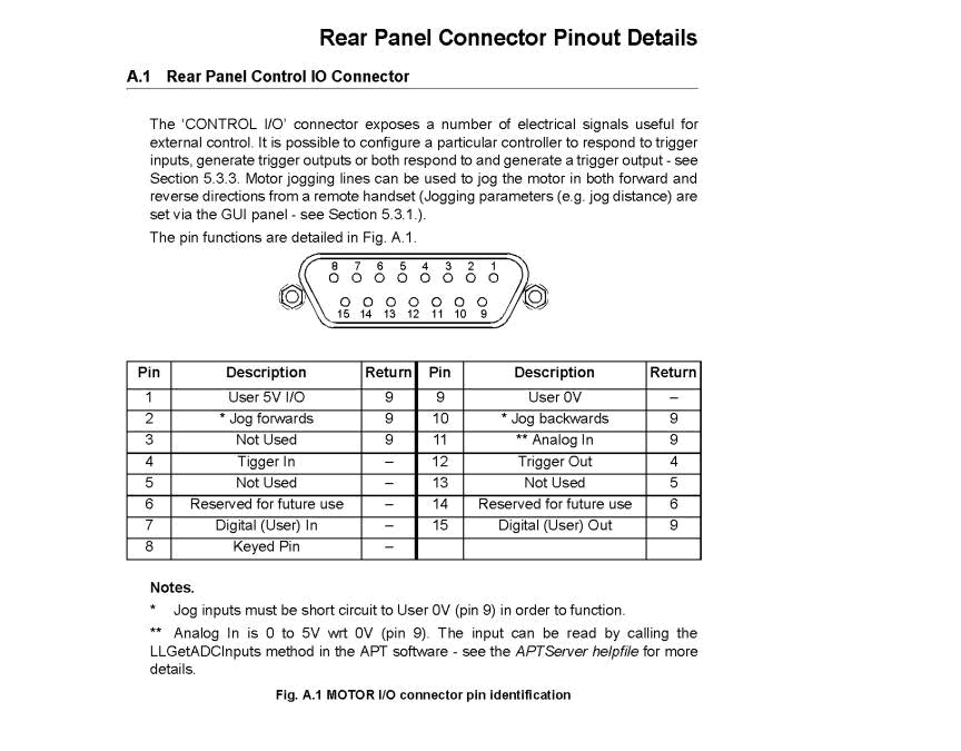
Hook-up the trigger, from the Thor controller "Control IO" pin for
"Trigger" to the NI input board Ain ch 3. Remember to include a reference
ground pin wire.
7. Now bring up and start (from IP folder) 8T_11_PulseRate.VI, which will wait
in its while loop for the trigger. Run the 8T_11_ThorController VI. On user
input "YES", the Thor controller should trigger and the other VI should
start collecting pulse data from a 9.0 Hz cardiac waveform into Ain ch3. Use
the charts in either front panel to check in real time that the experiment is
proceeding.
8. Run the plotting
function in work\Kelsey\Plot_Blaberus_8T11 m-file by typing this line:
>> close
all, [dt, times, positionsT, wave_times, waveformB] = Plot_Blaberus_11;
9. Now that you have
wave_times and waveformB available, write a matlab script or function that takes
those two variables and counts the number of "spike" events in waveformB
above a threshold thet. Have your function compute the max spike rate
(maybe run as input logrithmic sweeps of cardiac from 5-25 Hz)
Notes: turn on BSC-101 before starting ThorController.vi.
Max speed is 2.5mm/sec
with vi not running, practice jogging back and forth--watch
DRV-001 motor
Make sure the USB A-B cable connect BSC-101 to computer USB port
Trigger Out pin 12 to Ain of 8T_11_PulseRate.vi (ain 3...)
to fix VI need vertical arrays for sequence of steps for algorithm, from full
control menu...