Lab
9Q: Sensing Rotation with Optical Encoder, for use in studying Bimanual Knob
Rotation
A-path Lab
Background: You have completed Lab 9 by sensing knob rotation with potentiometers. Now you will try the same experiment with rotary optical encoders. The optical encoders here have no limit to amount of rotation they can spin in one direction; and the particular Bourns model used has much less rotational friction than a potentiometer (which need to scrap a "brush" along a resistive path to change the contact point of its middle "pot" pin...).
You will want to do Lab 9Q before Lab VT because in Lab VT there is a rotary encoder system detecting how a tooth gear rotates while the bike is pedaled.
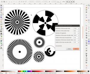
A rotary optical encoder has two offset black/white or transparent/opaque circular patterns; as the patterns are rotated around a central axis a light either reflects off white or shines through an opening for two photodetectors to signal one of 4 combinations of HIGH or LOW for any moment in time. See figures below
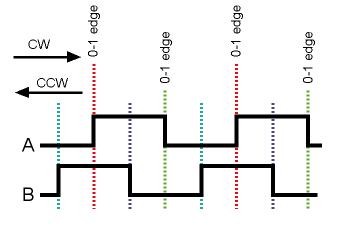
Time is the horizontal axis for the figure above; for CW it moves to the right,
for CCW time moves to the left. Notice above that when rotating CW a rising
edge on ch A occurs when B is HIGH; when the rotation in CCW A rises when B
is LOW. Taking advantage of that difference could allow you to mark 256 transitions
per full rotation, and know the direction of rotation.
Our rotary encoder--the
Bourns L00256L model--has 256 black/white changes in 360deg.
http://www.bourns.com/pdfs/enc1j.pdf
Our particular model is ENS1J B28 L00256L .
The color code for the wires on the
Lab 9Q frame is
Red: +5v
Black: GND
Brown or Blue: Channel A
Orange or Yellow: Channel B
Actually, the encoding scheme noted above doesn't work properly if the wheel is jittered back and forth. It can be improved/fixed by a "quadrature" algorithm that responds at the 4 edge changes and a counter goes up or down in response to each edge change.
Shown below is a snip of
code from modified Arduino sample code (HMJ
2011) for quadrature encoding:
void doEncoderA( ) {
A = (digitalRead(2) == HIGH) ? 1 : -1; //switch: if digitalRead
high, A = 1. if digitalRead LOW, A = -1.
pastA = A;
encoderPos = encoderPos + (A * -pastB); //handles all
4 recognized cases and all unrecognized in one line.
//A rising, B rising, encoderPos incremented.
//A rising, B falling, encoderPos decremented.
//
pastB = 0;
}
void doEncoderB(
) {
B = (digitalRead(3) == HIGH) ? 1 : -1; //see note above
pastB = B;
encoderPos = encoderPos + (B * +pastA);
pastA = 0;
}
Requirements:
(1) You may want
to attach the red and black power/gnd wires coming out of your Lab 9Q frame
to appropriate pins on the LabVIEW green connector board (Example: +5 comes
from pin 14; what should be "ground"? Connect two analog and digital
ground terminals together and make sure to run that ground to your scope...or
other device, such as DMM). Run scope probes to (say) yellow and blue leads
and spin the appropriate knob around; observe the Ch A, Ch B, offset responses.
Test each rotation detector, at the 68LP green connector card terminals
(2) Attach yellow, blue, orange, brown to LabVIEW inputs, from which you can create a VI, including DAQ Assist, that scans the 4 inputs simultaneously for 10 seconds. Multipoint WaveformS! You can scan either analog or digital inputs...
(3) Either with a Matlab script (see in Lab 8) or with suitable LabVIEW function icons, have a post-scan analysis of the 10 seconds worth of waveforms that results in positive counts for one rotation direction, and negative counts for the other direction.
(4) Show that a slow rotation of 360 deg results in a count increase of about 1024 (10 bit resolution). A rotation in the opposite direction takes you back to about 0 count, and if you keep going in that opposite direction one rotation the count will be about -1024.
(4b) If you rotate the knob as fast as you can, can your VI keep up with the faster data rate and show a correct 1024 answer?
DISCUSSION ABOUT SAMPLE RATE: If you rotate a knob here slowly, the data (count) will change slowly...and faster for fast rotation. In the case of back-and-forth knob rotation the speed should follow a periodic sinusoidal function of time. What you want--after having collected 10 sec worth of data--is to find the frequency of knob rotation. Because of varying sample rates sending the raw data directly into an FFT function is not appropriate.
One way around this: have post-data processing count the number of peaks in 10 seconds and divide that number by 10, for the dominant frequency of rotation. Subtract the mean of the raw count data from the raw count data itself to leave yourself with a cleaner sinusoid to analyze...
Another
idea: Sample your raw data at 40 Hz (every 2.5msec) and use that data set to
go into an FFT function...that would be a total of 400 data points, "equally"
spaced (perhaps by interpolation).
(5) Your quadrature algorithm will result in 10 seconds worth of time-domain data that you should process to figure out the dominant frequency in the 10 second run. Resolve to 0.1Hz.
(6) With your "better" knobs, collect (on a spreadsheet) data on tremor from at least 5 subjects. Have a subject hold the middle finger of one hand on the top of a knob (elbow held in space) with the instruction to keep the finger as steady as possible; record the resulting tremor/noise, or lack thereof. Try with one middle finger on the left knob and one on the right. Is the "noise" on the knobs correlated or not? Correlated in time we mean here... i.e. is the noise central or peripheral?
(7) Now we revisit Lab 9: Have each subject do an "in-phase" vs "alt-phase" test (in phase is both arms/hand using the same muscles at the same time...). Study your time-domain diagrams to make sure a subject doesn't switch form alt to in-phase during the alt-phase test. Do not allow "trembling" of small amplitude on the low friction knobs: Let's say the p-p amplitude of the back and forth rotation should be at least 64 or 128 clicks (out of 1024 for 360 deg).
(7b) Have each subject do an dominant vs non-dominant hand test, looking again for knob rotation frequency as the result, and p-p amplitude > 64 clicks.
(7c) Try a single-finger rotation vs a 3-finger grip rotation; which is faster?
(8) With Excel, use t-test with paired data to find the two-tailed significance of any differences.