Fan Lab: Control of Air Flow by Negative Feedback with Proportional, Integral, or Bang-Bang Compensation
The Fan Lab is on the A-path. As stated in the contract, there is no guaranteed help for the Fan Lab. The answer to your Fan Lab question "Can you help me with my circuit?" is "No, but can you rephrase?" Your next question is "I don't understand such-and-such a part of the Fan Lab writeup..." We can help you with clarifications all you like, but aren't necessarily going to help you troubleshoot lack of progress... other students may help out... but the TAs and I will soft-pedal serious troubleshooting.
A
subsequent "feedback quiz" is the FTQ for the Fan Lab. You must pass
the feedback quiz to qualify for an A using the Fan Lab as your extra lab.
Background: An electric fan can be a tachometer if the wires from the fan are hooked up to an AC voltmeter when sufficient air is forced through the fan functioning as passive "rotating machinery". You will close the loop on flow control and design a negative feedback compensation system to maintain a constant flow rate in spite of changes in the "environment" of the background fan. Your LabVIEW VI will control the voltage to a 2N4401 transistor base with a second small regulator fan in the "common emitter" path to ground.
As higher velocity air blows through a fan, the blades rotate more rapidly
and the wires connected to the fan show a greater induced voltage on a DMM.
Such a fan can act as a tachometer. Your goal: Control the air flow through
a fan-tachometer-wind speed detector so that changes in the "environment"
are compensated for by feedback, to keep air flow constant, as monitored by
the tach. The feedback, error detection, and error correction will take place
in LabVIEW, which will also send out a control signal for the compensating voltage
on an auxiliary fan. Your VI will have a set point control for determining what
the output flow should be. The difference between the set point and the tach
output is the error. You will need to study the output of the tach to determine
a reasonable set point voltage.
Requirements:
What to do first:
Find two of the small 5 volt, 0.25 amp computer fans, and one larger 12v fan. Connect
the three of them in series, with threaded 4-40 rod, so the flow from two fans blows
through and turns the blades of the third fan. The third fan will be used as a tachometer.
It may be better to have the
middle fan be the tach; see in your setup which arrangement gives a larger output
on the tach fan.
The Human Controller: Use the adjustable Agilent E3631A power supply to drive the large fan; try an initial setting of 10-16 volts. Make sure the polarity on the wires to the fan is correct, so the air flow is in the proper direction.
Before automating control of flow, find by hand flow conditions on the large and small fans that allow for the small fan tach to be compensated for a 1 volt increase or decrease in the large fan voltage. Start by hooking up your DMM to read AC volts from the tach fan. Drive the small fan directly from the 6 v. supply on the Agilent. Start by adjusting the large and small fan voltages until a "reasonable, stable" AC-mv signal on the tach is seen.
Pick equilibrium voltages
for the large and small fans such that when the large fan voltage is increased
1v you the human can find a lower voltage on the small fan that will take the
tach fan back to the original tach setting (mv-AC). Likewise for a decrease
of a volt on the large fan...where you the human can find an increased small
fan voltage that returns to the original tach setting.
Once you've found a good equilibrium, you are ready to automate the process!
The first step: Small fan controller:
See a design below for a transistor to control the current through the second
smaller fan. See suggestion below.
A 2N4401 npn transistor in
the emitter follower mode can drive the small fan; the small fan will be a load
from emitter to ground. Note the 20 Ω
current-limiting resistor on the collector. The collector has the 20 Ω
resistor and the base has the 100 Ω. The 12v shown on the collector R
can be as high as 16v...
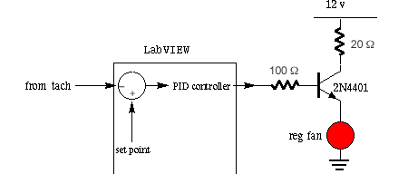
The base of the 4401 should be protected by a resistance of 100 Ω . The
base voltage on the transistor is normally about 0.7 v above the emitter voltage;
the base should be a positive Analog Out of 5 or more volts to drive the fan.
You may want to test your reg fan drive with the MAX software, and its Analog
Out, with Channel Update. See if you can get the emitter voltage above 4.5v
with Aout driving the 100 Ω at 6 or more volts. What happens when Aout
is 0, or even slightly negative? The reg fan should stop spinning, even if the
emitter voltage is not right on 0v.
You may need to bias the transistor driving the fan. That is, have a positive base voltage that the pure control signal algebraically adds to. It may work to have a collector voltage of 6v, from your triple output supply.
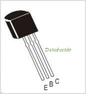
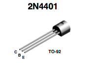
For pinout see below...for
more data on the 2N4401 go to the Digikey
website search and download the PDF file datasheet from Fairchild Semiconductor...
You may end up using a MOSFET
transistor to control current; check on parts available in the lab before deciding...
Tach Signal: Send the two wires from the tach fan to a 524 inst. amp
set for gain = 10. You should power the 524 from a "blue
box" so you are free to modulate the +12 on the Agilent supply.
With an oscilloscope, look at the output from the 524. The 524 output should be an irregular 500 Hz negative going waveform, of about 500 mV amplitude. Send the 524 output to a LP filter, to knock out the spikes in the original waveform.
(Optional: can go directly into LabVIEW with tach signal): Try a LF353
as a positive gain-of-two LP filter, as suggested below, or use an inverting
op amp with the LP filter in the feedback path...
If you send the 524 direct to LabVIEW, then recitfy and LP filter (average
100 points over 100 msec, for example...) in your VI.
Have the filtered (and possibly rectified) signal go into LabVIEW and be displayed on a chart. You will want your tach signal to have most of its ripple removed, so it is a low frequency signal going to the comparator.
Compare the tach signal with
a SET point from your VI control panel. Compare by subtraction! The result,
in your LabVIEW VI diagram, is the ERROR signal. The error signal can then go
to a test bed of "Proportional and Integral" control in your VI. The
"forward pathway" should have some gain > 1.
The result, finally, will be an ANALOG OUT from the green connector box that will control the base voltage of the 2N4401 transistor (or MOSFET) which in turn regulates the current through a small auxiliary fan.
Between error generator and the fan control circuit you may want PI compensation. Consider the principles of negative feedback when designing your flow control compensator. Study the lecture notes from the 123 website and the references available in the lab. Design a compensation system to speed up the response, and reduce tach output oscillation. Consider compensation in the form of integration of the error (increase the control signal until error is zero) and/or derivative of the error (large control signal for changes in error). Since the motor is so slow in its response, a 1Hz cutoff may be about right for either filter. Derivative control may be more difficult to manage that integral, proportional or bang-bang.
Block diagram: The block diagram below shows a general form for automatic
control of flow rate; "gain 10" is the 524 inst. amp. The path from
the tach leading up to the summation point may need to be offset or rectified, too.
In the compensation block you would need more gain, and possibly integration
or bang-bang limits (see below). The fan control circuit has a transistor to control
current to the small "regulating" fan.
Use
of LabVIEW for controlling compensation.
Send the tach signal into LabVIEW, where it will be compared to a SET point
and an error will be calculated. The compensation network will process the error
and the result will go to an analog output headed for the base of a transistor
controlling the "regulator fan". (Your VI may also want to send a
slow square wave signal to the SET input on the comparator).
What you need to demonstrate: If the voltage to the large fan is decreased by 1-2 volts your automatic controller should be able to return the tach output to within 5% of its set point in 20 seconds or less; likewise if the large fan voltage is increased by 1-2 volts. If I put my hand in front of the large fan to decrease inlet pressure, the automatic control should be able to compensate. In addition, you will show that negative feedback is necessary for the control. Turn down the gain of the proportional controller or spread out the "window" limits on the bang-bang controller, then show that changing the voltage on the large fan causes uncompensated changes in the tach signal in LabVIEW. That is, demonstrate that if you try the disturbance experiments with the loop open (no feedback)the system will not compensate to maintain constant air flow.
FTQ: WAIT FOR THE FEEDBACK QUIZ AFTER THANKSGIVING!
Student example of proportional control VI diagram:
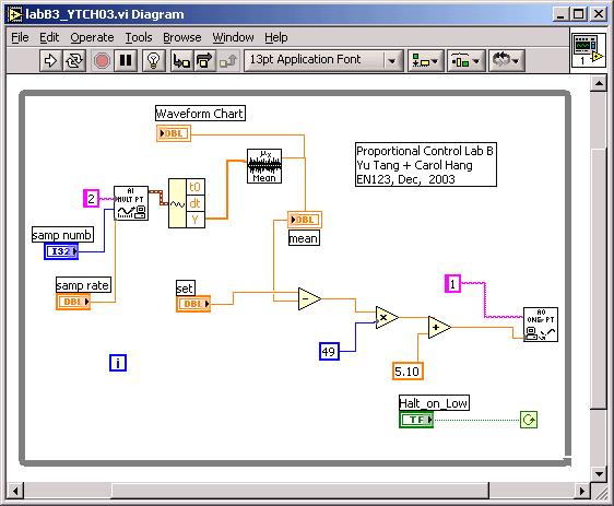
Sample the 524 channel for a fraction of a second
(good guess: 100 msec or less). Take the average over that interval.
Apparently the students who made the VI above had a tach waveform with a non-zero
average, possibly due to a rectifier before entering LabVIEW. Otherwise you
can place an |absolute value| icon between Y and mean. Another way:
Build a low-pass filter on the output of the 524. Note that the filtered tach
signal goes into the minus of the subtractor: Negative feedback! The 5.10 v
is their equilibrium voltage for the small fan; yours might be different!
The 49 is their "open loop gain." If 49 is set to 0, the system is
"open loop."
EXTRA: We will try to have available a hot-wire anemometer for measuring flow speed of the air coming out of the fan system. Graph the relationship between applied voltage and wind speed. It should be nonlinear: rotation speed of fan proportional to applied voltage and speed of tach proportional to square of wind speed.
Proportional-Integral compensation: Add a path parallel to your proportional compensation which integrates error. Multiply the "summation with shift registers" by a number less than 1. Add proportional and integral together. Show what happens when you turn on integral control. Read lecture notes for more detail.
Free Advice: The blue box will supply the +12 to 15v to the 2N4401 and the +/- power for 524 and possible op amp. The Agilent power supply will be the variable supply for the large fan... make sure all "reference" grounds are connected...
Shown below is the diagram panel of a bang-bang controller, telling
you how to unbundle the waveform output of a single-point AI icon. The AIn reads
the tach output from the 524. The "0" index item in the resulting
array is the most recent data point.
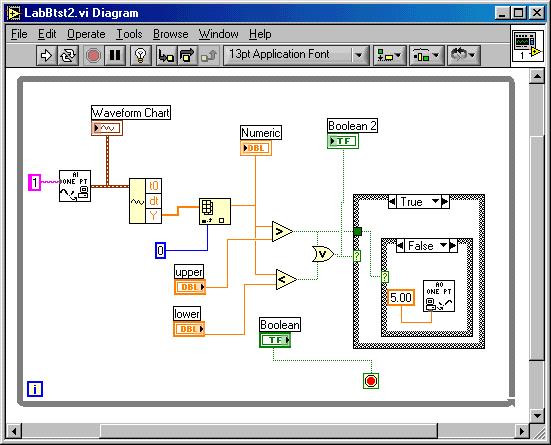
"Upper" and "lower" are two tach readings that will trigger
the small fan to change; in the "False" of the outer Case is a default
Aout set to 4 volts; if the tach value falls below the lower threshold the small
fan voltage drive is increased to 8 (or 5) volts; if the tach value goes above
"upper" then the small fan control is set to 0 volts. This strategy
is neither proportional nor integral, but a more primitive bang-bang control
to drive the flow rate back into range.
Demo for bang-bang controller: If we spread out the distance between the upper and lower limits of the controller, we will watch the tach response "triangle wave" between upper and lower.
Troubleshooting. It is important to verify that your small fans work properly. First drive the small fan through Aout of MAX, with the big fan turned off and the tach rotated out of the way. Can you hear or see the small fan rotate? Then put the fans back in series and modulate the small fan as you try various "middle range" values for the big fan. You are searching for an equilibrium point. If you use a 4401 transistor, it may heat up while driving the fan. Try to use 12v (instead of 15v) for the small fan collector voltage, or increase the collector resistance to 33 ohms. .
Score 2 more points each for showing PI (proportional-integral) or bang-bang control solutions.