Lab
0.5: Window Discriminator
Background: Neuroengineers,
when recording from small groups of neurons, have the problem of discriminating
a single neuron's waveform from others being recorded simultaneously. One help
is a window
discriminator: a circuit (or VI) which responds after it detects
a pulse whose height is greater than a minimum threshold and less than a maximum
threshold (thus the pulse height is in a window between 2 thresholds).
Requirements:
A. Create a LabVIEW virtual instrument (VI) which reports after it
has seen an analog-in start below threshold-1
(thet1), then travel above thet1 then drop below thet1 without having
moved above thet2 (thet2 > thet1).
Hysteresis: Because the analog-in signal may carry noise we allow that the
drop-below version of thet1 can be about 10% less than the travel-above threshold.
Therefore once the signal crosses above thet1, it must drop somewhat below thet1
before triggering a valid pulse detector.
Your input will come from
the variable 6v-max selection on your triple output Agilent Power supply. Arrange
that the minus (reference, ground) of the 6V supply goes to (say) terminal
64 (an AIGND) of the green connector block, and the plus on the supply
goes to pin 30 (ACH3, analog channel 3 (in case ch1 is blown).
Generalizing
what you learned about DAQ Assistant in Lab 0, use DAQ Assist to set up an analog
input channel which will receive 0-6v from your Agilent power supply.
Testing your VI: Your VI panel
will have exactly two controls, one for thet1, one for thet2, that we will set
to reasonable values. We will set the initial value of the input to somewhere
between 0 and 6v. You start your VI. We will vary the input voltage, testing
that when we run it below thet1 then just above thet1 then below again, you
circuit detects ONE event. Your VI will run at least until ONE valid event is
detected. That event will be signaled with a Boolean indicator light on, on
the front panel. See Figure below: The black line waveform is an example of
one way we can vary the input analog signal.
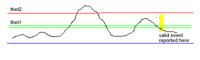
In the figure we run the signal level above thet2, then back down below thet1:
an invalid event; then run the signal just above thet1, then down below the
hysteresis level, at which time your VI lights a boolean indicator. You're successful
if the only the second event is detected.
Reasonable values for thet1
< thet2 are 1 and 2 volts.
Free Advice: Read about LabVIEW while loops, frames (Structures menu,
and analog input (Data Acquisition menu). Understand what it means to be a dataflow
language (one while loop at a time running). Before you hook up a real analog-in,
you may want to test your while-loops VI with with a front panel control...
Make "Local Variable" copies of the front panel slider, and converter
them to READ if you wish to pursue this test.
If you seem to be having trouble reading analog-in from
a particular channel, bring up MAX, the "Measurement and Automation Explorer"
(yellow arrow over blue ribbon), which allows you to use the Test Panel to exercise
6024E functions without invoking LabVIEW. On the left side, find 6024E under
Devices. Click on 6024E and look for Test Panel on the top menu. Select Properties
analog-in properties make sure "Reference Single Ended = RSE" is chosen.
Don't leave Test Panel open while LabVIEW
is running.
When you have a VI with a DAQ Assistant in place and giving no wiring errors,
you will find it puts out a "waveform" data type that may need to
be converted to single value floating point (thin orange). One way: pass the
waveform through a max/min detector from the Array menu. Another way: pass the
waveform through a "Get Waveform Components" icon in the Waveforms
menu of the Diagram, then an Index icon from the array menu. See
examples of unbundling here. Another way: send the waveform into a comparator
and select "Compare Aggregates" when you right-click on the comparator.
You may want to establish a series of frames: inside an "outer" while
loop. Suggestions:
In the first frame consider a while loop looking for a signal below thet1, and
Stop If True.
Next frame: Look for signal greater than thet1 and Stop If True.
In the third frame two things can happen:
1. If the signal next goes below the hysteresis value, exit the current while
loop, light the indicator, and return to the first frame;
2. If the signal next goes above thet2 then exit the in a way that starts the
signal back at the frame 1 "inner loop" without lighting the indicator
or incrementing a counter.
LabVIEW 2013: For the point 5 lab challenge example worked
in class, when using DAQ Assist in the lab, on the third panel, you will
likely need to place a "From DDT = Convert from Dynamic Data" on the
output of the DAQ Assist, choosing "Singular Scalar" when you double
click on the DDT icon. This action converts the "dynamic" output of
DAQ Assist to scalar data that the comparators and logical OR of the panel will
accept (on the way to controlling the red Stop If True while button...)
Find DDT from the Express/Signal Manipulation part of
the Functions palette...
As a troubleshooting aid, you might want to have digital indicators on your
Panel for each of the inner loop index i's.
You can design all the logic using a digital control as the input, and sending
the control by Local Variable Read to each of the inner while loops. After the
logic works, switch to the analog input from the Data Acquisition Menu.
Extra Credit: Note that the requirements don't say anything about sensing
more then one valid pulse event. For extra credit (meaning you don't
have to answer a FTQ to pass this lab), show us a VI that can run continuously
and can count how many valid pulses it has seen. Hint: consider using shift
registers on the outer while loop. Continuous pulse counting will be required
for the Roach Leg Lab.
Each student should do Lab Point 5 alone, and save it
with your initials in the file name, in the My Documents\EN123_IP_201X folder.
After finishing Point 5, pair up with (be assigned to) a lab partner.