Lab Zero: LabVIEW Exercise with For Loop and Analog Out
Requirements:
A. Create a LabVIEW virtual instrument (VI) that adds up the numbers
0.1 to 1.1 (in steps of 0.25) with an initial condition on the sum of 0.15;
each time another number is added to the sum, the VI will pause for 2 seconds.
Show the current sum as a numeric indicator on the Front Panel of your VI: it
will change once every 2 seconds while the VI is running.
B. Arrange that the current sum is used to generate an Analog Out signal
on channel zero, and that your DMM (Agilent digital multimeter) shows the DC
voltage from the output pin vs ground. The voltage will appear on pin 22 of
your green connector board. (Where is ground for your measurement? try pin 55
or 56...) Thus every 2 seconds another voltage reading will stabilize on the
DMM.
C. If you arrange that after the start of your VI with "the white arrow" the first reading on the DMM is 0 volts for at least one second, then no FTQ.
How accurate is the DMM at displaying the LabVIEW output as
voltage?
How are your numbers like the Fibonacci
sequence?
Each student should do Lab Zero alone. After you demonstrate Lab Zero we will ask you a "fault tolerance question", and once you answer it correctly we'll sign your scorecard. At that point, please use the text tool to enter your name and the year on the front page of your VI. Name your VI with your initials and save in the My Documents EN123_IP_201X folder...
Now you can proceed to Lab Point 5.
Free Advice:
You will want to read about LabVIEW FOR loops, and their shift
registers for iterating outputs back to be inputs on the next cycle of
the loop. See pp. 69-78 of Mihura textbook, or the LabVIEW tutorial that accompanies
the software installation, or the LabVIEW Users Manual on the www.ni.com website,
chapter 8.
To generate an analog output
* Find the DAQ Assistant icon by using the the block diagram Functions Menu--at the top of the bottom see Measurement I/O: slide off onto NI-DAQmx; on that menu look for DAQ Assistant (lower left area).
* Once you get that icon on your block diagram and click on it and up will come a window that asks: Acquire or Generate signals? Choose Generate. Choose Analog Output.
* Up will come a window showing tab Physical. At the top of the white space it should say Dev1 (PCI-6024E). Choose "voltage" then ao0 then click Finish.
*
You're back to the first DAQ Assist screen. On the Generation mode (left side)
menu choose 1-Sample! At the bottom right click on OK.
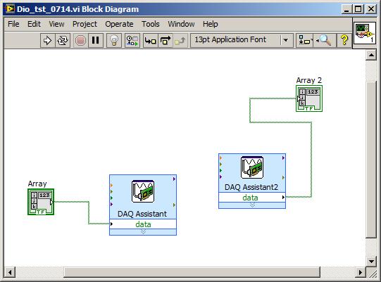
LabVIEW will crank through several seconds of "Building VI." Now
you're ready to connect the red lead from the DMM to "pin 22." to
the DMM input. Below
is a screen shot (from Lab 4Pre) which gives you the general idea
The Time & Dialog menu of the Functions palette should have a delay function
you can use.
Although a printout of it should be in the lab near each computer, you can look up the pinout of the green connector card by searching for 6024E (DAQ card) on the www.ni.com website. Try the Dec. 2000 version of documentation. Or just look here!
You can test that the Analog Out channels are working properly (independent of LabVIEW) by using MAX Measurement and Automation Explorer (yellow arrow crossing blue ribbon icon near LV icon on desktop).