Electrical Safety, Grounding,
Noise, Shielding and Isolation.
Product safety & liability: "Eventually, every product fails." Consider
the pyramids. The pyramid at Giza was built about 4500 years ago, but within 500
years it had failed in its mission to safeguard the treasures of Pharaoh Khafre,
because of grave robbers.
Effects of current on humans: 60 Hz,
each arm gripping an "electrode", about 3 sec duration
demo with variac
1. 0.5 to 2mA, threshold of perception:
is it a vibration? a tingle?
If my resistance is 100K, then at about 50 V RMS I will feel a tingling sensation,
on the Variac.
2. sensation
of pain 2mA to 10mA
3. Let-go
current 10 to 50mA: forearm muscles stimulated, and flexor muscles dominate, unable
to let go of electrode
4. Respiratory
paralysis 50mA and up. Diaphram unable to relax
5. Ventricular
Fibrillation 50 mA to 2A cardiac muscle does not contract in a synchronized
way. likely fatal unless defibrillation used. Actual current through the heart is
much less: maybe 100 microamps. A device like a pacemaker or a cardiac pressure
sensor, placed close to the heart, can be guilty of a small leakage current and
be dangerous to the heart.
6. Burns
above 1A. may increase or decrease skin resistance.
See Fig 14.1 in Walter H. Olson chapter, "Electrical Safety, pp 751ff in Webster
(ed) Medical Instrumentation (1992): Work of former UC Berkeley advisor Charles
Dalziel.
Three effects can occur when the body becomes part of an electrical
circuit:
muscle contracts
sensory neurons begin reporting pain, including due to...
heat, leading to burn of epidermis
JD Harry: Critical parameter is not current, but current density
through particular tissue.
AC to cause contraction of muscle, sensation in pain receptors, burning of tissue
DEMO: GROUND STRAP
Testing 9 v battery on tongue...
http://www.cdc.gov/niosh/elecepid.html
is a website that discusses on-the-job death by electrocution. 99% are male.
http://www.ccadp.org/electricchair.htm
is a website on the history of the Electric Chair, and the controversy between Edison
and Westinghouse.
Ground vs neutral Demo
In a power cord the black wire is hot, the white wire is neutral and the green
wire is ground. The neutral wire carries the return current from the hot wire, while
the ground wire should carry no current; it is reserved for shielding and a GFI
reference. If I touch the white and the green wires of a plugged in power cord,
i should not get a shock, if everything is wired up correctly.
Ground Fault

Ground fault interrupter (GFI)
DEMO. First understand that current on hot wire must equal current on neutral
wire. If not, there must be leakage out of ground wire or out of patient to ground.
Next appreciate that hot and neutral wires wound through a differential transformer,
in such a way that they cancel outeach other if both currents are the same. If hot
and neutral current don't cancel, then there is nonzero primary current and B field
in transformer: resulting in a stepped up secondary voltage that can be rectified
and amplified to activate a mechanical breaker switch that trips off the HOT wire.
See Fig. 14.16 of Olson, differential transformer, or :
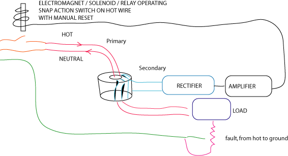
Exhibit 2 GFIs procured from Home Depot, Lowe's. See
the differential transformer.
Isolation for patient
protection
by impedance: UGVF
optical
by transformer-data sheet on Analog Devices 293...2500v isolation
direct in-line protection:
fuses, circuit breakers, GFI.
iso-switch, cuts out at 50 uA
demo: resistor to ground (27K vs 1.5MW)

Notes on Power Supplies
Batteries for low noise
decoupling capacitors
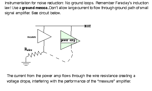
avoid ground loops
isolation circuit breakers transformers optical isolators isolation amplifiers
from Analog Devices website
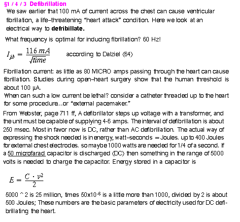
The diagram below shows a possible design
for a defibrillator. See Webster page 713, Fig 13.11 for another version of
the circuit...
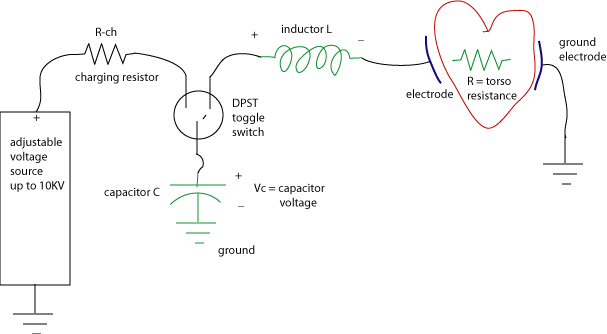
A capacitor
is charged to store the necessary Joules of energy to be discharged across the
torso/heart, modelled by the resistor on the right. When the toggle switch is
flipped from CHARGE to SHOCK we want all the energy to pass through the torso,
but we also want to control the duration of the discharge. Adding an inductor
in series with C and R, the torso resistance creates a second order circuit
and gives the designer another parameter to control timing. What would be wrong
with adding a resistor in series where the inductor is? The inductor can store
magnetic energy, but, like the capacitor, does not dissipate energy.
Next comes the math necessary to develop
the equations and formulas that reveal the timing of the circuit: Use Kirchoff's
current law. There are two nodes: one between the capacitor and inductor, and
the other between the inductor and the resistor. We assume you remember from
the tutorial, or your exposure to circuits, that 1/sC is the Laplace transform
version of capacitor impedance and sL is the impedance of an inductor. When
the switch is flipped there is an "initial condition" v-c(t=0) on
the capacitor voltage that enters into the first node equation:
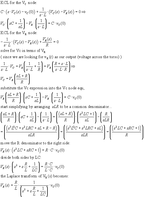
Next focus on the denominator of the
transfer function, to find the natural frequencies and time constants of the
GFI circuit...
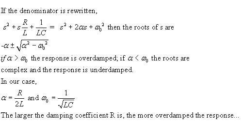
If alpha = omega0 the system is critically
damped.
In class a model will be demonstrated
using SIMULINK (jdd/SecOrd123_etc)
that shows graphically what to expect from the voltage/current across the torso
as a function of time, in various cases. Multiply
the second integrator output by R/L to get correct voltage, which is squared
and divided by R to find Power through torso. Integrate Power to find total
energy delivered. In the simulation the R/L factor is brought in for calculating
the correct power, to be integrated for total energy in XXX msec (set in Simulink
time-end box).
Coupling
Conductive coupling (ground chains)
Capacitive coupling (wires running near each other)
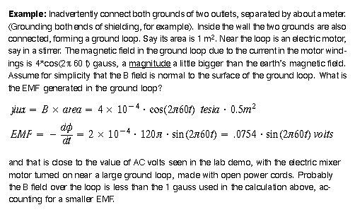
Inductive coupling (loops that enforce Faraday's Law)
Ground loops can be the source of more noise because of Faraday's Law, that changing
magnetic fields through a loop can induce EMF.
Inductive coupling
Where do magnetic fields come from? from motor windings in refrigerators, mixers,
etc.
SOLUTION to inductive coupling: TWISTED PAIR. Why does twisting
work to reduce inductive coupling? There's still the same area facing the B field
lines. Check out direction of da vector! As you twist two wires into a pair
of loops" the a vector points in different directions, thus giving a sign change
to the flux, and making algebraic sum of flux closer to zero.
B field is measured in Tesla; a gauss is 10^-4 Tesla.
Faraday's Law says
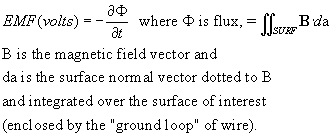
Note: Defined in terms of the E field, voltage is

where P is the point w.r.t. ground that the voltage is being measured from. Voltage
is independent of the path from ground to point P.
See Griffiths, p 286 for discussion of Lenz's Law, and the "jumping
ring" demo, which references the minus sign in Faraday's Law.
Shielding
Electromagnetic radiation, from 60Hz on up, can enter wires when they
act as antennas. Solution: Shielding by metal foil. Faraday cage.
Intended to combat the pickup of EM radiation by wires; can be
from AM radio, florescent lights, etc. More difficult to shield for magnetic fields.
Shielding means surrounding of a cable by a metal foil one side of which is
grounded. Why only one side? To prevent ground loops! Why does shielding work?
Think back to your E&M course: The potential in a metal is constant
everywhere, and the field inside is therefore zero.
 ; shielding
makes the gradient zero...
Don't place your sensors and signal conditioners near motors or
radios or cell phones or pulsed lasers...
Less noise in cooled resistors
As the temperature of a carbon resistor increases, the resistance may drop a
little, but white noise and shot noise increase, and in proportion to the size of
the resistor. What is white about white noise? All frequencies!
A 1M resistor will pick up or generate much more noise than a
1K resistor. One solution: Cool sensors. Another, lower the output impedance of
devices that must drive long transmission lines. Thus the output impedance of a
UGVF: For a change in output current, how does the output voltage change? If not
much at all, then output impedance is low. How to measure output impedance of an
active device? Attach load that attenuates signal by half; such a load will be equal
to the size of the impedance.
From Derenzo, page 61-62, "Sources of noise"
*White noise has equal power in any frequency interval
*pink noise has equal power in each frequency decade
"Johnson noise is white noise voltage developed across a resistor
due to the thermal agitation of the charge carriers (electrons) within the resistor"

where R is the resistance, B the bandwidth and kT the usual boltzmann constant
x temperature. If resistance increases by an order of magnitude, Johnson noise
will increase by

For B = 106 Hz, R = 10^6 Ω Vrms = 129mV , more than 0.1 mV.
(Shot noise)"The
concept of shot noise was first introduced in 1918 by Walter Schottky
who studied fluctuations of current in vacuum tubes. Shot
noise may be dominant when the finite number of particles that carry energy
(such as electrons in an electronic circuit or photons in an optical device)
is sufficiently small so that uncertainties due to the Poisson distribution,
which describes the occurrence of independent random events, are of significance.
It is important in electronics, telecommunications, optical detection, and fundamental
physics." from Wikipedia. high energy electrons and photons are
more likely to cause shot noise...

Electrical interference. A 1-m long unshielded wire
can pick up 100 microvolts of noise...
Walter Olson (of Medtronic) chapter in Webster
Electrical/radiation accidents a year in hospitals result in 10,000 injuries
per year.
Medical personnel rarely read manuals until a problem occurs;
and eventually all devices "fail" so fail-safe mechanisms need to be designed.
Murphy's Law...
The big problem: mucous and skin are exposed and open in hospitals...
EM radiation, including x-rays, falls into the category of electrical hazard.
Other "beneficial" use of electricity:
Electroshock therapy for treatment of severe depression.
high current ( amps AC) across the brain. brief AMPs pulse.
EMS for toning up muscle...
but this is DC
PROMOTE WOUND HEALING...
Fig. 14.12, micro-shock hazard. What if connection to green
ground is broken?
2 faults: ground broken, and bed touches hot...
Fig 14.15, grounding system for proper care.
Fig 14.7: wire color code for neutral and ground connections.
See ground fault interrupter, Fig. 14.9
electrolytic fluid (blood, saline) can cause short circuits when spilled on equipment.
short circuit from power to patient contact points (chassis, iv line, etc)
QUESTION: WHAT IS A MICRO SHOCK HAZARD?
Absence of electrical power can be a problem: need back-up generators...
Bahill, p. 255 ff
"The motor windings of a vacuum cleaner are often exposed
to damp dust, which then provides a path from the hot line to the case."
"Equipment ground should not be confused with patient ground,
which is used to reduce noise."
Gary Johnson, "Grounding and shielding" pages 52
- 59
"Ground. The absolutely most overused, misapplied, and misunderstood
term in all of electronics."
Horowitz and Hill, chpt 7, "Precision circuits and low-noise
techniques"
Difference between dynamic range and precision. A log amplifier
may have great range on input, but only modest precision.
Error budget: A rational approach to adding expensive precision
components.
Precision resistors: A precise circuit starts with precision
resistors. Example of metal film 1/2% precision resistors: H&H say why you should
use them instead of hand selected carbon composite resistors: better stability over
time. See appendix D of their book. 301K is generally the maximum value available
in precision resistors.
Leakage across capacitors: In some circuits, capacitors
are required to hold their charge for a considerable time (sample and hold circuit...).
Need to know about dielectrics for capacitors: polystyrene, polycarbonate, polysulfone
are the best.
Noise reduction by eliminating the noise instead of filtering
it.
Horowitz & Hill page 307-313
pp 286-312: amplifier noise vs "interference"
amplifier noise: p 292-293: "en drops and in rises with increasing Ic"
implies optimization
Legal Issues of Safety: Negligence, Malpractice, Expert
testimony, "inherently dangerous".
Underwriters Lab
Note on FDA Regulation of BioMedical Instrumentation:
Another Bureaucracy, another false sense of security?
Summary List
*effects of electric current on the body
* GFI and differential transformer
*GROUND MECCA
*SHIELDING: electrostatic & magnetic
*ELECTRICAL ISOLATION OF PATIENTS
*EM radiation X-rays, microwaves, power lines...
Cromwell page 330: 20uA can fibrillate a dog's heart; human open
heart surgery: 108uA
OLD OUTLINE
why three wires
ground fault interrupters...in the modern bathroom
consider a tree=shaped ground system
avoid ground loops
have a ground MECCA
Isolation-optical, transformer...AD293A
fuses...
Tompkins & Webster (eds) Interfacing Sensors to the IBM PC chpt 2 page
34...
Bahill's book, current chart on page 256
PROTECTION FROM em RADIATION
See JD handout from May 5, 1981
SUSCEPTIBILITY OF PATIENTS WITH BREAKS IN THE SKIN, TO I=V/R
Static electricity hazard
sparks for explosive gases CMOS chips damaged
NO carpeting in patient areas, or in labs!
Electromagnetic hazard
x-rays, microwaves, ultrasound burns from
radiation; damage to DNA.
pre 1990 Notes...
current flowing on ground
resistance of "ground" wires ground loops
SOLUTIONS (black magic?)
avoid radio stations, elevators, subways, arc welders
& high power pulse lasers
shielding low level/high W wires
ground only one end of the shielding...
guard electrode-a follower drives an inner shield, keeping 0 v difference between
the signal and its surrounding
twisted pairs of wires (reduce magnetic coupling)
try BATTERIES
Why is it important to keep analog and digital
ground lines separate?
Noise from clocks on the digital side?
signal noise (through high W)
"small signals and long wires"
enter through output wire...
"noise" on power line
voltage developed across ground...IR
capacitive (electrostatic) coupling (H&H, p.307)
ELECTROSTATICS AND CMOS...
magnetic coupling through induction
EM coupling (radiofrequency range) through wires acting as antennas


