Knowing strain, stress can be calculated (Hooke's Law):
Strain Gauges
Strain: Consider a bar of "rigid" material L cm
long. Under longitudinal stress the bar will change length ΔL. ΔL can
be negative or positive, depending on whether the bar is in tension or compression.
Strain is ![]() ,
a dimensionless ratio; a measure of deformation due to length change dL.
,
a dimensionless ratio; a measure of deformation due to length change dL.
Knowing strain, stress can be calculated (Hooke's Law): ![]() where E is Young's modulus, a material property, with dimensions of Force/Area,
same as stress (pressure). Length and force are normalized in the stress-strain
expression.
where E is Young's modulus, a material property, with dimensions of Force/Area,
same as stress (pressure). Length and force are normalized in the stress-strain
expression.
Example: Bone has a E of about 100,000 psi. 10 psi of stress
will stretch a 20 inch femur ![]() ,
not much!
,
not much!
Strain gauges measure small length changes.
Elastic vs plastic deformation. Elastic deformation
returns to zero-stress shape after stress is removed. Plastic deformation: "permanent"
change in shape due to stress.
Other sensors for length change:
Piezoelectric material: vibration sensor. (rate of change of length)
Optical
measure of
strain, by interference. Prof Clifton helped pioneer this technology.
Brittle lacquer applied to a surface: then monitor where the lacquer cracks.
Is a tape measure a length sensor?! Consider Laser-based tape measures.
Potentiometers for measuring angle change.
Reading: "Practical Strain Gage Measurements",
HP Appl. Note 290-1.
S. H. Derenzo, Interfacing: A Laboratory Approach..., Prentice-Hall (1990)
pp 169-170
Poisson's ratio: When longitudinal tension stretches a
shape, the transverse dimension shrinks.
 from
screensaver.com
from
screensaver.com
Transverse strain: ![]() captures the shrinking (or expanding, in the case of compression) of the transverse
dimension, which we signify by the letter D (diameter). Poisson's ratio η is
captures the shrinking (or expanding, in the case of compression) of the transverse
dimension, which we signify by the letter D (diameter). Poisson's ratio η is
![]()
note the minus sign! Poisson's ratio is a material property.
Finding Poisson's ratio: If a material maintains constant
volume during stretching, what should η be? Say we're dealing with a rectanguloid
of material of length l and side s. take differentials and set dV = 0: no change
in volume.


![]()
Now what? remember that strain is dl/l :
Therefore a 0.5 Poisson ratio is for completely incompressible material. An
example: rubber! An example of nearly zero Poisson ratio: Cork! Plexiglas, it
turns out, has a Poisson ratio of 0.45. No material has a ratio greater than
0.5. Most metals are in the range of 0.3.
http://silver.neep.wisc.edu/~lakes/PoissonIntro.html
Work out what the Poisson ratio is for a 1x1x1 cube stretched-without necking
down-to a length of 2...
V=l x s2=1, so when l=2, s drops to 1/sqrt(2) = .707, resulting in a ratio of
about 0.3...
What would happen to volume if transverse strain were
zero but longitudinal strain were positive? The material being stretched would
have increased in volume...
Resistance related to strain: development
adapted from Don De Voe, Univ Maryland, ENME 489F — Intro to MEMS
Consider a material with resistivity ρ of rectanguloid shape of length L
and sides S. Then its resistance in Ohms R is
Resistivity ρ has units Ohm-cm, and may be variable, such that the last term above is not zero.
Consider the common sense of the formula above: if the length increases a little, then resistance increases a little. If the transverse dimension increases a little, then resistance decreases a little.
What about the piezoresistivity term, ![]() ?
It is normally not zero. In fact for some semiconductors it dominates the expression
on the right of the equation. For metals, with a Poisson ratio around 0.3, nonzero
piezoresistivity basically results in approx:
?
It is normally not zero. In fact for some semiconductors it dominates the expression
on the right of the equation. For metals, with a Poisson ratio around 0.3, nonzero
piezoresistivity basically results in approx:
![]()
The ratio of resistance change to strain is
![]()
and is 2 in the example above.
When you purchase a particular strain gage
the vendor will list the exact Gage Factor. We use BLH
and Vishay strain gauges in the lab. See p.
17 of Transducer Gage catalog for our 90 deg pattern SGs.
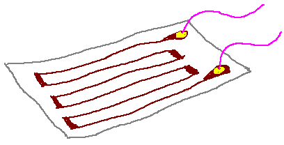
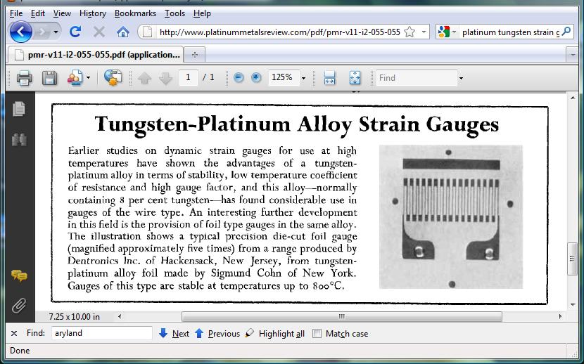
The bonded foil strain gauge is one of the most important transducers in the realm of engineering. The strain gauge metal is attached firmly to a strong flexible insulating transparent sheet. That sheet in turn is bonded by epoxy to the material whose strain should be measured.
A strain gauge is often formed in the serpentine shape shown
below. [In the BLH strain gauges for the EN123 Lab, sometimes the thin foil
is nickel chromium alloy.] Along the vertical axis a change in each segment
L by length DL results in a 14* ΔL change in total length of the strain
gauge!
 from www.sensorland.com
 another
graphic: from www.natmus.dk
another
graphic: from www.natmus.dk
Look closely at one of the strain gauges in the lab and see if
the serpentine pattern shown above is evident. You might see two strain gauges together,
in a "rosette" pattern.
As the bar is stretched the transverse dimension decreases.
Practical note: Each individual SG has an unloaded
resistance of either 120Ω or 350Ω, notice with your Ohm-meter how
close to the R0 value an unloaded strain gauge is!
The change in transverse-oriented strain gauge resistance
is ![]()
Another important reason for using rosette pairs of strain gauges is compensation for temperature effects. The amplifier is really using the ratio of resistance changes; to the extent that self heating or other common temperature effects change both resistances, a ratio of the changes will remain constant. This technique is particularly valuable on materials, like fiberglas, with low thermal conductivity.
Calculation for microstrain amplifier
and if the gauge factor is properly used with the strain gauge amplifier, it
basically tells you you can find what strain e is directly
(in microstrain, x 10-6). (See additional sheets.) For R=350 and Vp = 15 volts,
I find a gain of 7000 or so for reading out directly in microstrain...I used
the approx that
where, as shown below, R+DR is the resistance of a strain gauge in the lower
leg of one side of a bridge and the voltage divider output of that leg is
Why is the beta approximation true? We show below, using Taylor series expansion:
try it: if R = 120 and delR = 1, then (120+1)/(240+1) = .5021, and .0021 is
1/4 of 1/120...
see Thomas, Calculus and Analytic Geometry, page 785 ff
see matlab file sg123.m for calculations based on formula.
2004: Next: a different derivation
of ΔR/4R, avoiding Taylor series, thx to Univ Maryland website referenced
above:
which is the term we found to finish the expression for Vout
= G*Vex*ΔR/4R for one strain gauge in a "positive" location in the
bridge.
Analyzing more than one active strain gauge in the bridge:
An active strain gauge is on the material and can be deformed
by stress. There may be other strain gauges in the bridge, as precision resistors
for temperature compensation.
If there is one longitudinal strain gauge at position R1 then VOUT = VEX*G*&DeltaR/4R;
Placement of 2 gauges for compression or bending: Examples:
Now consider compression-tension vs bending. Imagine gauges
can be on front or back of material:
Longitudinal strain gauges on front at R1 & R2: will respond to bending:
gain will be VEX*G*ΔR/2R
Longitudinal strain gauges on front at R1 & R4 will respond to compression-tension:
with gain VEX*G*ΔR/2R
Suppose R1 is longitudinal front and R2 is longitudinal back side: Now best response for bending.
Remember that longitudinal and transverse strain are related by Poisson's ratio. If there are longitudinal and transverse gauges on the same side (front, say), then they should be at R1, R4 to sense compression.
4 gauge example: See the crude diagram below: With reference
to the Wheatstone bridge above, the notation is as follows: TL means Top Longitudinal,
BT means Bottom Transverse, etc.
Say the longitudinal strain on top and bottom is .001. On top it will be positive,
on the bottom it will be negative. Say Poisson's ratio for the Rod is 0.25. Say
the excitation voltage is 6v and the gain of the differential amplifier is 100.
What is Vout?
On the left side of the bridge R1 increases and R3 decreases,
both contributing to the left input to the amp increasing. On the right side
R2 decreases and R4 increases, both contributing to a decrease of the right
side input. All 4 gauges are working in the same direction.
(2008) A table to list all possible influences of single strain
gauge placement on a multiplying factor of deltaR/4R:
For the table, here is the assignment of Resistors numbers to the bridge:
| TABLE OF INFLUENCE OF STRAIN GAUGE ON VOUT,� | AS A MULTIPLE OF deltaR/4*R | |||||||||||||||
| Assume Vout is gauche (left) minus right side of bridge.� | ||||||||||||||||
| LG = longitudinal gauche | TG = transverse gauche | LR = longitudinal right | TR = transverse right | |||||||||||||
| R1 upper gauche, R2 lower gauche, | �R3 upper right, R4 lower right | |||||||||||||||
| Assume eta = Poisson's ratio is 0.25 | ||||||||||||||||
| R1 | LG | TG | LR | TR | ||||||||||||
| R2 | LG | TG | LR | TR | ||||||||||||
| R3 | LG | TG | LR | TR | ||||||||||||
| R4 | LG | TG | LR | TR | ||||||||||||
| tension down� | -1 | 1 | 1 | -1 | 0.25 | -0.25 | -0.25 | 0.25 | -1 | 1 | 1 | -1 | 0.25 | -0.25 | -0.25 | 0.25 |
| CW bend | 1 | -1 | -1 | 1 | -0.25 | 0.25 | 0.25 | -0.25 | -1 | 1 | 1 | -1 | 0.25 | -0.25 | -0.25 | 0.25 |
Bonding of strain gauge to material
Want high fidelity contact
of strain gauge to material under study. Adhesive: want to minimize its effect
on SD deformation. Can use a thin layer of adhesive: that means cyanacrylate,
which bonds one molecule thick. "Superglue" may be susceptible to
chemical attack, such as acetone. In addition, cyanacrylate may be less stable
than epoxy, a more chemically inert alternative. Epoxy is good for bonding to
wood.
Notice there's an up and a down side for each SG set! What about the wires that lead away from the strain gauge? They may need to be strain-relieved. twisted pair.
Noise and grounding problems in strain gauges
Consider placing the strain gauge "foil" on a metal base with
cyanacrylate. There will be capacitive coupling, significant because of the
small d in the eA/d = C formula. There may be leakage to the metal base ground
(conductive coupling) through the plastic foil.
Temperature compensation
Use strain gauges for all 4 resistors in a bridge! Then any temperature
change in the experiment will be completely compensated for. Except that the
material under study may change also, due to temperature...but that may be part
of the experiment, to study expansion due to temperature. Can't invoke Hooke's
Law in that case.
Also may need to worry about resistance changes due to self heating. V2/R for 10 volts and 120 ohms is nearly a watt! A SG bonded with epoxy may be less able to dissipate heat than its partners in the bridge.
High-Temperature SGs:
http://www.vishaypg.com/docs/11532/highpat.pdf
and
Strain gauge amplifier: See yellow box strain gauge amplifier box in the lab. You may remember it from EN3, or EN31.
Strain gauges and temperature: self heating; or heat from the bulk material the gauge is attached to.
Link, from down under:
http://me.queensu.ca/Courses/215/Mech215-Lab4-StrainGauges.pdf
Summary
* definition of strain, stress, Young's modulus
* Poisson's ratio for incompressible material
* definition of resistivity
* Strain gauge in a bridge circuit
* Taylor Series approximation : delR/4R
* Temperature effects on SGs and the underlying material
*
-------------------- ------------------ ------------------
Archive notes:
Piezoelectric materials: charge displacement q = K*f when
  the material is stressed. And a nonzero rate of change of rho with strain.

Speed of response
What limits speed of response of the strain gauge? Capacitive coupling may be one thing.
 May want to measure vibration (and you will, in Lab 7). At what frequency can  a metal rod vibrate?

* types of position  measuring devices: example of Virtual Reality exoskeleton

Application of length sensors: how to sense hand and finger position
in a virtual reality glove. Optical sensors in fingers? find a
website! Compare muscle spindles to strain gauges.


  1988: Volume 2 Berkeley Physics page 128, CONDUCTIVITY graph

The strain gauge amplifier can be set up to take account of both axial and transverse
  responses, so that the effective gauge factor for the measurement is


  For the metal material used in our gauges, Ks = 2.0
Constant current for bridge excitation See HP Guide to Strain Gauges, page 14.