Temperature transducers and Peltier coolers
Sept. 2008
Ubiquity: When it comes to temperature sensors, the world provides us with
an embarrassment of riches: Every material responds in some way to a change in temperature:
change density, change color, change resistivity, change thermal conductivity...
Here we explore some of the material changes beneficial for instrumentation sensors.
Specs: accuracy; speed of response; spatial localization. We want change
in temperature to result in a voltage change. Liquid crystal fever strips and mercury
bulb thermometers don't qualify as "instrumentation".
Temperature dependence of materials
Free valence band electrons in a heated metal find their mean free path reduced,
thus metallic resistivity increases.
When they're given more energy by heat, some outer shell electrons
in nonmetals (semiconductors and insulators) move into the free valence band and
thereby lower the resistivity of nonmetals.
Diode Current: What to make of the current-voltage
relationship for a semiconductor diode?
Yike! It looks like when temperature goes up, current goes down, implying an
increase in resistance! What can rescue us? It turns out that Is (reverse bias
current) depends on temperature too. For every 5 deg C increase, Is doubles.
Where Is0 is a fixed small current, about 10^-12, and Tref is "ambient"
temperature, or reference...
If temperature doubles from say 200 to 400 deg C, diode current increases by
about 10 orders of magnitude.
More detail on semiconductors: The Boltzmann relationship
states that the number of electrons in the conduction band depends on temperature
with the function exp(E/kT), where E is band gap energy for the material. As
T increases, the Boltzmann factor increases.
Platinum temperature standard: From Derenzo, page 157:
"Platinum is a noble metal that can withstand high temperature and harsh chemicals
with good stability."
A platinum wire carefully cut to have exactly 100Ω of
resistance at 0°C changes resistance according to

Thus a 10°C change in temperature results in a little less than 4 ohms increase
in resistance.
Bimetallic strip
Take advantage of different coefficients of thermal expansion. Weld together
strips of different metals. The strips can be wound into helix or coil for more
angular deflection.
Derenzo has a table of thermal expansion coefficients
for different metals and alloys:

Above is definition of thermal expansion. Note STRAIN in the numerator.
Bimetallic strips are used in many low-cost rugged temperature sensors (meat thermometers,
etc.). They can be placed in on-off electrical circuits where they close or open
a current-carrying wire.
Metals are excellent for this application because they have large thermal expansion
coefficients, they can be joined together easily, they can flex without breaking,
and they can conduct electrical currents without overheating.
Question: Does the mechanism above have hysteresis? Maybe
it has "thermal inertial"...
nitinol DEMO: Nitinol is an allow of nickel and titanium.
It is a temperature sensitive shape memory alloy: A mechanical temperature effect.
Used for vena cava clot filters, and arterial stents, for example.
perfect mechanical memory when heated to set temperature. At a higher temperature
the nitinol can be formed into a new memory shape.
see
http://www.nitinol.info/pages/technology.html
Thermistors
Reading: See
Boctor & Ryff preprint, Chpt 10, p. 26 ff, on thermistors, and
S.E. Derenzo, Interfacing, Prentice-Hall (1990), p. 165 ff. and
http://www.thermometrics.com/assets/images/ntcnotes.pdf
(result of typing "thermistor tutorial" into Google)
Thermistors are basically sintered semiconductor material
exhibiting the Boltzmann relationship.
Thermistor are 2-terminal (not polarized), unlike a semiconductor
diode junction.
You will use, in the lab, negative temperature coefficient
NTC thermistors.
Resistance of the thermistor, RTh, at
absolute temperature T, can be calculated by
where R0 and T0 are reference resistance and temperature, and TE is a property
of the semiconductor material used to make the thermistor. Boctor and Ryff suggest
a nominal value of 4000 deg K, where the other T's in the formula are also to
be expressed in degK. If ambient temperature is greater than reference temperature
then the exponent is negative and the factor multiplying R0 is less than one,
as you would expect for a semiconductor material.
Thermistor self heating
If you know R0, T0, TE, and T (the ambient
temperature) then you can use the above formula
to calculate the expected thermistor resistance RT. Because some
current must flow through a thermistor for it to provide a measurable voltage,
power will be dissipated and heat generated. Enough heat can noticeably raise
thermistor temperature (above ambient). If ambient
temperature is constant and current has been flowing through a thermistor for
a while, then the thermistor temperature will have reached equilibrium of convective
heat transfer (other types of heat transfer: conductive, radiative).
In the steady-state case,

where Tamb is the ambient temperature (usually air or
water). "Area" is the surface area of the thermistor and hconv
is the convective transfer coefficient with units of Watts/(cm-sq*deg
K). The coefficient is a property of the material boundary (thermistor-air in
the case we will consider). The equation says that the amount of power being
"absorbed" by the thermistor due to I^2R Joule heating must equal
the amount of heat convected away from the surface of the thermistor.
At any rate, the steady-state temperature
of the thermistor will be
where Tamb is the zero power calculated temperature
(apparent temperature) and Ttherm is the actual temperature
being measured. Approx values for hconv
and "Area" are .02 and 0.1cm-sq, for a factor of about
2 mW/°C. If 5 volts drops across 500 Ω then the thermistor will be about
25 deg hotter than the air! Recall a formula for power across a resistor is

DEMO:
A 300 ohm thermistor in series with a 100 ohm resistor is connected to a 9 v supply.
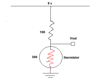
When the voltage across the thermistor is measured just after power is applied;
it's about 6.7 volts. In a minute or so Vout drops below 5 volts!
Time constant of self heating: dynamics.
Before power is applied the thermistor is at ambient temperature. As power
is dissipated by the resistor after the power is switched on, the thermistor
absorbs heat until it reaches thermal equilibrium. The following first order
rate equation balances energy transfer (Joule/sec = Watts = power)

First notice that when ΔT = 0 the steady condition is revealed. Otherwise
the thermistor heats up with a time constant of

where Hs is the specific heat of the thermistor material and Mass is
its mass in gm. Notice the common sense of the time constant formula: if the
thermistor is larger, or the specific heat greater, it will take longer to heat
up; if the area of the thermistor is great, or the convection coefficient is
large (thermistor in water instead of air) then equilibrium will be reached
quicker.
The specific heat*mass is analogous
to the area of the bucket in a a leaky integrator, or the size of a capacitor
in a parallel RC circuit.
Specific heat has the units of Joules/(deg-gm); for example the specific heat
of water is 1 cal = 4.18 J/gm-degC 4.18 Joules of heat will raise the temperature
of one gm of water one degree C.
http://www.allmeasures.com/Formulae/static/formulae/specific_heat_capacity_300K/28.htm
is a website that gives the specific heat of silicon.
Estimate the weight of a thermistor:
If the time constant of our self-heating demo really is 60 seconds,
and hconv x Area = .002 and the specific heat of silicon
is 0.7 J/gm-deg,
then what is the mass of the thermistor, in grams?
ans: 60*.002/.7 = 170mg = 0.17 gm;
by the density of Si (2.3gm/cc) that would mean the thermistor takes up about 0.07
cc...
Dynamic
Example. Consider
the 9v power supply driving a 100Ω in series with a 300Ω thermistor,
shown above. What happens to Vout(t) when the power supply is first
turned on?
Say the ambient temperature = T0 = 293 degK. Certainly at t=0 Vout = (3/4)9 = 6.75v.
But after that the thermistor will heat up and Vout(t) will decline, as you saw
in the class demo.
Let's see how power delivered to the
thermistor is calculated:
Power depends on Rtherm in 3 places, and Rtherm
depends on temperature T in a nonlinear way. We will have a nonlinear differential
equation to solve. The equation's "time constant" will likely be near
the formula for TAU above, but the exact form (and
waveform of Vout) will be more complicated. How to proceed? One way: Simulate
the equation with a tool like Simulink, itself an iconic "simulation"
of an analog computer, and a part of Matlab.
Rewrite the diff equ above, isolating the
first derivative of ΔT on the left side:
The input to the integrator (1/s) is the derivative, as expressed on the left side
of the equation.
A Simulink model for the diff equ is shown
below:
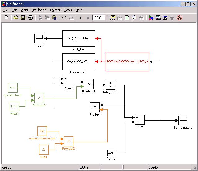
Simulation results will be shown in
class. Understanding this self-heating model may be basis for an oral quiz after
Temperature Lab #5.
Note: In the lab you can find the real
ambient temperature by a calibration procedure instead of a calculation! In the
case of Lab 5, that means you need to worry about placement of the calibration probe:
the thermocouple.
Tradeoff: Lower resistance thermistor more
susceptible to self heating, higher resistance thermistor more susceptible to noise
and parallel conductance (aqueous placement).
Thermocouples:
Imagine two dissimilar metal wires, about a meter long, that
you have welded together at one set of ends. You have created a thermocouple. If
you hook the other 2 wire ends up to a very sensitive DC voltmeter (like the Agilent
in the lab) you can detect a mV size voltage (EMF), that is sensitive to changes
in temperature.
Websites:
http://web.engr.oregonstate.edu/~aristopo/temper.html
some background material, considering energy bands.
http://www.internetfred.com/thermo/thermo.html
"A thermocouple with one junction of pure platinum and
the other of 90% platinum and 10% rhodium is often used in high accuracy, or high
temperature applications. Of course, platinum thermocouples are also
expensive. Copper and constantan are frequently used when the desired accuracy does
not justify the cost of platinum." from Dwayne Rosenburgh
on www.madsci.org website
For copper/copper-constantan thermocouples, the EMF would be
1.19 mV at 0°C and 5.71 mV at 100°C.
Constantan is a nickel alloy.
Diffusion-Drift EMF: Consider first the voltage developed
across the junction of two dissimilar metals. Assume the (negatively charged)
electrons in metal A have higher mobility than those in metal B. Electrons
from A will diffuse across the junction until an EMF arises prevents
further diffusion. The EMF will cause electrons to drift in the opposite
direction of the diffusion. In the "passive" version described above
the result is called the Seebeck effect; when the charges involved are
forced across the junction by external voltage, it is called the Peltier
EMF (more below)
We will see a similar diffusion-drift balance when we consider
how Nernst potentials (voltages) develop across nerve cell membranes, due to
ionic imbalances: Jdiff + Jdrift = 0. In the case above, A and B are
connected to a high-impedance voltmeter to reveal the thermocouple EMF.
The relationship between mobility
µ and diffusion coefficient D is
When temperature rises, D always increases while µ increases for non-metals
and decreases for metals. Further information: in F. Reif, Statistical Physics
McGraw-Hill, New York, (1967), page 337 shows that, in general,

So even though mobility in the metal decreases for increasing
temperature, diffusion increases exponentially and the Peltier EMF increases
as temperature increases. (pers comm R. Pelcovitz).
Thomson EMF: If one end of wire is heated, the more
active electrons at the heated end will "diffuse" (thermal conduction)
toward the cool end, setting up a Thomson EMF. For the situation above, the
wire A will have a greater Thomson EMF from heat at the junction, because its
electrons are more mobile.
The Thomson and the diffusion-drift EMFs add together to make the junction EMF
larger when heat is applied. More technically, the junction EMF is a half-cell
that requires special treatment of the loose A and B ends to measure properly.
Seebeck EMF is sometimes referred to as the sum of Peltier and Thomson EMF's.
Maintaining reference. The reference junctions
need to be kept at a constant temperature for an accurate reading. Can be done by
wiring to remote reference, in a lab setting, where 0 deg C is the standard. How
is it done with the Fluke 52? Compromise: near room temperature, measured internally
with a thermistor, and feedback used to adjust output. What happens to initial
output if the Fluke 52 is kept in a freezer for an half an hour? What happens when
the DMM records a thermocouple voltage, then a hair drier is aimed at the reference
connection?
Advantages of thermocouples: Can be used at higher temperatures
than thermistors. No self heating.
Thermopile: thermocouples in series.
Kasap
on voltage calculation for thermocouples
Cool Demo: cooling by Peltier effect.
go to website
http://www.tellurex.com
for more information on the devices we demonstrate in EN123.
Observe the series electrical connection of parallel semiconductor junctions in
the device.
You will see a thermoelectric structure capable of handling 4 amps at 16 vots =
64 watts.
Bismith telluride is the semiconductor involved.
Images below from Tellurex website tutorial:
Mechanism: If electrons are forced from the
low mobility to the high mobility side, the effect is like an expanding gas in a
refrigerator, and the junction will be cooled.
Another way of saying it: electrons pumped from the low mobility
side to the high mobility side will absorb heat as they cross the junction, and
the junction will be cooled. As the circuit is completed through two junctions of
dissimilar metal, then one of the junctions will heat up and the other will cool
below ambient temperature.
A Peltier cooler has biomedical applications in locally cooling
tissue. "Cryosurgery."
<Joule
effect is I^2*R heating of a material.>
Temperature-Sensitive Liquid Crystal: JD recalls experimental
method of measuring brain surface temperature by reflecting green laser light off
of cholesteric liquid crystal smeared on brain surface.
Temperature sensors and control in mammals: All cells in
mammals are affected by temperature in one way or another, but some cells, due to
special membrane proteins, are exquisitively sensitive.
¶ Two locations for mammalian temperature sensors: skin and hypothalamus. (Peripheral
and central.)
¶ In the skin are two types: sensors for warmer than normal and sensors for
cooler than normal.
¶ Warm range: 30-45 deg C. cold range 10-35 deg C. Once
skin is taken below 10 deg C, cold receptors stop firing and cold becomes a good
local anesthesia.
¶Firing rates of skin sensors obey power laws as a function of temperature.
¶ Temperature-sensitive fibers headed to the spinal cord have lower conduction
velocity: 1-30 m/sec.
¶ Skin sensors send signals back to the spinal cord, where they may eventually
affect local circulation.
ref: Bear, Conners, Paradiso, Neuroscience, Williams and Wilkens (1996)
pp 316-320
NEGATIVE FEEDBACK:
¶ If hypothalmic neurons sense temperature less than normal, response may be
increased metabolism, or increase muscle activity, including shivering.
¶ If hypothalamic neurons sense core temperature greater than normal, they
trigger cooling response: like cooling by evaporation of sweat.
¶ Increased core temperature may be due to athletic activity, or fever. Fever
is due to toxins released by infecting bacteria or virus. The toxins affect membrane
proteins of the temperature sensitive neurons. Normal feedback response to higher
temperature may not ensue during fever. (new set point)