 ENGN1300: Mechanics of
Structures
ENGN1300: Mechanics of
Structures
FEM Truss Analysis Program.
Truss.mws is a two-dimensional finite element truss analysis code,
written in MAPLE. It is quite general, in that it can handle an arbitrary
number of joints, members, loads, and boundary conditions. The program
illustrates how simple the matrix truss analysis is to implement. The worst
parts of the program are those that involve the graphics!
The code reads an
input file which specifies the coordinates of all the joints, the connectivity
of the members and the
relevant material and geometrical data
for each and the boundary conditions and load conditions. The input file must
have the following format:
Run
Title
Number
of joints (nodes) N,
![]() coordinate
of node 1,
coordinate
of node 1, ![]() coordinate
of node 1,
coordinate
of node 1,
![]() coordinate
of node 2,
coordinate
of node 2, ![]() coordinate
of node 2,
coordinate
of node 2,
…
![]() coordinate
of node N,
coordinate
of node N, ![]() coordinate
of node N,
coordinate
of node N,
Number of members (elements) M,
For element 1: 1st node number, 2nd node number , value of EA
For
element 2: 1st node number, 2nd node number, value of EA
…
For
element M: 1st node number, 2nd node number ,
value of EA
Number
of prescribed displacements L,
Node number of 1st prescribed displacement, component (1 or 2), value of the
displacement,
Node number of 2nd prescribed displacement, component (1 or 2), value of the
displacement,
…
Node number of Lth prescribed displacement,
component (1 or 2), value of the displacement,
Number of loaded nodes K,
Number of first loaded node, force component ![]() ,
force component
,
force component![]()
Number of second loaded node, force component ![]() ,
force component
,
force component![]()
…
Number of Kth loaded node, force component ![]() ,
force component
,
force component![]()
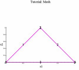
On the screen, you
are asked the pathname of the input file. A picture of the truss with node and
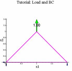
element numbers shown, is displayed, as is the truss
with vectorial representations of load and boundary
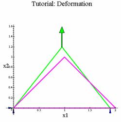
conditions. If these look correct, hit return and the computer will display a
deformed truss and plot of the truss showing member forces. If you then provide
a pathname for an output file, the numerical values for nodal displacement
components, member strains, and member forces are printed to it.
In the ABAQUS truss tutorial,
you analyzed the following simply supported statically determinate truss:
![]()
![]()
An input file for
analyzing this problem with the Maple program is shown below.
Tutorial
3
0.0 0.0
1.0 1.0
2.0 0.0
3
1 2
1.0
2 3
1.0
3 1
1.0
3
1 1 0.0
1 2
0.0
3 2
0.0
1
2 0.0
1.0
Here are the graphics Maple shows on the screen once it has read the input
file:
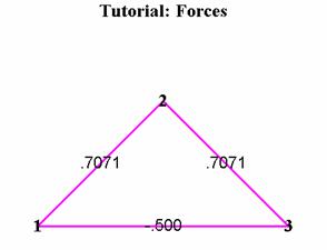
After the
computations are made, these graphic results are displayed:
The output file produced
after running the program looks like this:
Tutorial
Number of Nodes and Elements: 3 3
Node# x1 x2
1
0.0000 0.0000
2
.7070 .7070
3
1.4100 0.0000
El# Node 1 Node 2 EA
1 1 2 1.0000
2 2 3
1.0000
3 3 1
1.0000
Fixed Node# DOF Value
1 1 0.0000
1 2 0.0000
3 2 0.0000
Loaded Node# P1 P2
2 0.0000
1.0000
*********************************
Nodal
Displacements:
Node
u1 u2
1
0.0000 0.0000
2
-.3490 1.3461
3
-.7029 0.0000
Strains and Forces:
Element Strain Force
1
.7051 .7051
2
.7071 .7071
3
-.4985 -.4985
The code itself is divided into 10 main sections:
1) Read the input
file and set up data structures to store nodal coordinates, element
connectivity and boundary conditions
2) Graphically
display the problem as understood by Maple.
3) Define the
element stiffness matrix
4) Define the
element residual vector
5) Assemble the
global stiffness matrix
6) Assemble the
residual force vector
7) Modify the
stiffness to account for constrained degrees of freedom
8) Solve the FEM
equations
9) Display the
results graphically on the screen.
10)Write results
to a file.
To run the
program: Place your curser in the top comment area, and hit return. Before
hitting return, however, be sure that you have given give the full pathname of
the input file in the line indicated by the comments. Backslashes must be used
in place of front slashes in the pathname. The file name and path should be
something like /u1/blumeja/tutorial.inp.txt. Maple will then print the output
to a file called /u1/blumeja/tutorial.out.txt. This output file will be created
if it isn't already present. If it is, the output will overwrite the existing
file.
You can download a
copy of this Maple file by right clicking here. You
should use "save target as..." to save the file as Truss.mws. The input file for the tutorial truss
is available by right clicking here.
You can try a
number of tests to understand how the program works. You can add print()
commands to print out any intermediate variables you like – for example, you
could examine each element stiffness matrix as it is added to the global
stiffness, or print the final global stiffness matrix. You can also do tests
like computing the determinant of the global stiffness (The determinant should
be zero before the boundary constraints are added. Can you see why?)
Here is a full listing of the program. Those sections devoted to graphics are marked as such. It is a good idea to look at the listing for the non-graphics version of the program. This will enable you to concentrate on the nuts and bolts of coding finite element calculations. To download the actual non-graphics maple worksheet, right-click here.