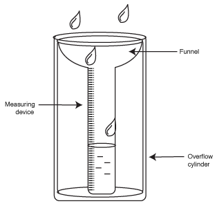
Consider first the rain gauge, as an introduction to the hydraulic analogy for electricity.
 www.infoplease.com
The
Leaky Integrator, and capacitance C.
Consider
first the rain gauge, as an introduction to the hydraulic analogy for electricity.
www.infoplease.com
The rain gauge itself is a cylinder of constant area, with enough height to
accommodate the rainfall for the climate it is in. Instead of raindrops imagine
the constant flow Fin cm^3/sec of water from a pump to tubing above the
cylinder.
In the hydraulic analogy the cylinder is a capacitor. The bucket (cylinder)
integrates flow and represents it by the water's height.
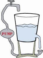
Next,
behold the leaky bucket: See below. (Pretend the bucket has a
constant area A over its height). Like the non-leaky rain gauge, flow of Fin
cc/sec is filling the bucket; as water height increases, so does Fout from the
leak.
 (dwg
by RISD student Jo Schulak)
(dwg
by RISD student Jo Schulak)
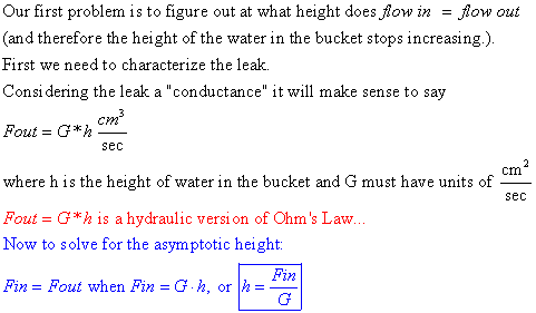
The answer for asymptotic
height makes
sense: More flow in, greater height; bigger leak, lower height.
Next we want to
figure out how long it takes to reach the asymptotic height. Actually what we
want is a more "engineering" time constant, the time it takes to fill
to within 1/e of the asymptotic height. For this time we need to solve a differential
equation:
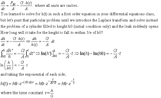
Again: the time constant A/G makes sense: If area A is larger it'll take more
time to empty each cm of height, and if G is larger the emptying will take place
faster...
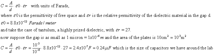
In order to match up the math for the leaky integrator above with an electrical circuit of resistor and capacitor, we need to give you information about capacitors.
A capacitor consists
of two conducting plates each or area A, separated by a non-conducting gap d.
Then
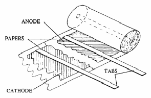
Electrolytic
capacitors and power supply decoupling:
Nothing we have said about what a capacitor
is suggests that it matters at all which end of the two-terminal device you
place at higher voltage node of its branch in a network. An electrolytic capacitor
has an ionic conducting fluid (the electrolyte) as one of its plates, effectively
to increase the capacitance for a given volume.
 http://electrochem.cwru.edu/encycl/art-c04-electr-cap.htm
The electrochemistry of the fluids requires one side of the capacitor to be an anode and the other to be a cathode, resulting in the capacitor being polarized: one side (+) must be higher voltage than the other side.
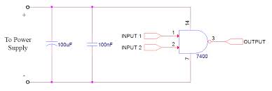
Electrolytic capacitors find use in decoupling power supplies: The capacitor is simply run from the + side to ground, and acts as a charge reservoir/low pass filter. Power supplies can carry noise spikes caused by clocks, switches etc, and this noise is absorbed by electrolytic decouplers.
 www.capacitorguide.com
The capacitor
symbol on the left, with the curved lower edge, denotes a polarized capacitor
decoupling the power supply of a NAND logic gate; decoupling capacitors are
best placed physically near the circuit components that need protection from
or are sources of noise.
Measuring capacitance. Our Agilent 34401A multimeter, as expensive as it is, has no capacitance measuring mode. We do have other handheld mulitimeters in the lab that can measure capacitance, in the range microFarads to nanoFarads. Basically capacitance value is determined by measuring the time constant of an RC circuit with a step response input. You can do the same thing in the lab with series RC circuit, a waveform generator, and an oscilloscope.
Capacitors aren't marked with anything as standard as the resistor color code. Nor are 100 capacitors of a certain size in a drawer as closely valued as even 2-cent cost, 5% tolerance, resistors. 20% tolerance isn't uncommon.
Stray
capacitance: In
a way parallel to how leakage resistances arirse, stray capacitances becomes
unwanted circuit elements that can contribute to noise and reduce frequency
responses of amplifiers. Take the example of coaxial cable:
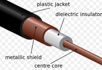
The cable, which can be many feet long (or much longer, in the case of underwater
transmission cables) has a metallic shield to keep electromagnetic radiation
away from the center core wire. But you can appreciate an inadertent capacitor
is created in the process, with the insulater of the wire acting as the dielectric
of this "cylindrical capacitor."
Sometimes called parasitic capacitance in the case of integrated circuits(like your LF353 op amp) or PC boards, stray capacitance arises from signal wire traces laid over ground planes and separated by thin insulating layers.
A useful
variation of such integrated circuit capacitance is the capacitive touch sensor,
as diagrammed below: The close presence of a finger increases the sensed capacitance.
See website below for more detail.
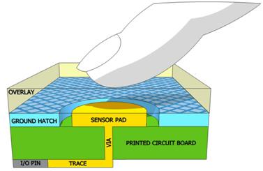
http://www.embedded.com/design/connectivity/4401019/Capacitive-sensing-for-advanced-user-interfaces
Laplace
transforms (math interlude)--
As you may recall from a diff eq course (AM33),
the Laplace transform takes you from the time domain to the frequency domain
and allows you to solve a differential equation algebraically.
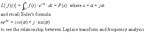
A property of the Laplace transform, given you know F(s), the Laplace transform
of f(t):
The Laplace integration property: ![]() ;
see
;
see
http://www.swarthmore.edu/NatSci/echeeve1/Ref/LPSA/LaplaceZTable/LaplacePropTable.html
for more properties, including the Laplace transform of
the time-shifting.
Example:
another way to define/calculate
capacitance: C = Q/v; Q = C*v ; I = C dv/dt, where Q is charge and v(t) is voltage,
then
![]() to see that sC is the admittance Yc of a capacitor.
to see that sC is the admittance Yc of a capacitor.
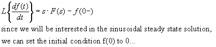
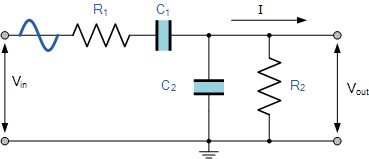
and this "differential" form will be used to find out how a capacitor
works in the "leaky integrator" circuit below:
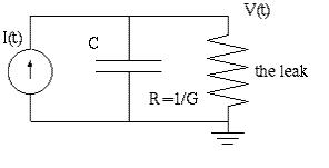
Here are "all steps shown" for the Laplace transform solution
by partial fraction expansion: Assume v(0) = 0.
You've now seen the leaky integrator solved as a straight time-domain diff eq,
and by way of the Laplace transform method.
In the node-admittance-matrix format the Laplace transform of a linear circuit would look like
V(s) = T(s)*I(s) where T(s) is the transfer function and describes in node-admittance form the circuit and I(s) is the Laplace transform of the current source inputs; V(s) and I(s) may be column vectors.
Furthermore, if the input is sinusoidal, and we want amplitude and phase information about the outputs, the these pages from Nilsson (4th Edition) McGraw Hill (1993) will tell you why we can substitute jω for s and work through the result. Note that frequency in the case described comes out as radians/sec.
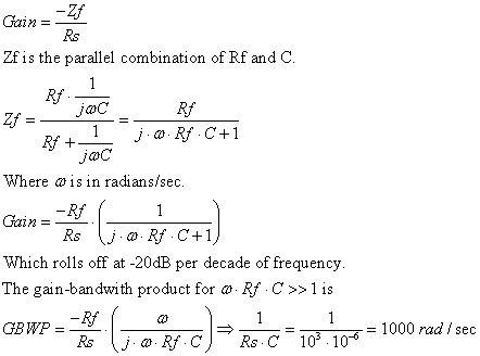
With this notation in mind, consider how the Lab 1 Gain-Bandwidth problem can be seen in Laplace transform terms for a parallel RC feedback circuit:
Op Amp Parallel RC Example: Below, a R-C network in the feedback loop of a
negative-gain op amp:
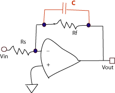
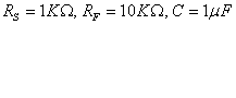
To calculate the Gain Bandwidth Product (magnitude) of the circuit as a whole,
and considering
the op amp itself has a GBWP > 10^7 rad/sec >> than GBWP of circuit
as a whole:
---------------- --------------------
The
hydraulic analogy again:
* voltage is like water pressure
* current is like water flow
* electrical resistance is like resistance to water flow through a pipe
* Capacitance is a reservoir of water
Note that the water in the cylinder represents stored energy: Example: the water behind Hoover Dam has the energy to turn the power-generating turbines at the bottom of the dam. It turns out that the energy stored in a capacitor is:
![]() ;
;
A fact of importance when we consider the design of a defibrillator later in the course; Energy is in joules, and about 300 joules for 250 msec is needed to defibrillate the heart.
Capacitors don't dissipate energy and heat up, like a resistor, they store store the energy, and a large enough capacitor can function somewhat like a battery.
What about the conductance leak at the bottom of the bucket? Does water flowing
through a pipe dissipate energy like a resistor's I^2*R joule heat? Does the
interface of the pipe and the water heat up? The answer is yes (hat tip to Prof
Vlahovska)
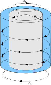
but not by much, because water has such low viscosity. Prof Richardson offered
an example of a higher viscosity fluid where heating up is significant: lubrication:
A test bed is two concentric cylinders, one rotating inside another, separated
by a high viscosity fluid:
 physics.stackexchange.com
The smaller the separation (R2-R1 above) between the two
cylinders, the more heat generated in the lubrication interface.
Formulas
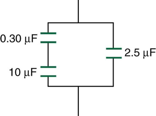
for capacitors in parallel: CT = C1 + C2, in series 1/C = 1/C1 + 1/C2.
Consider two equal capacitors in series as increasing the dielectric
thickness by a factor of 2...
What's the capacitance below?
Capacitor as a frequency-dependent "resistor": if I = jwC (w being radial frequency of a sinewave input), then capacitors are "short circuits" at high frequency and "open circuits" at low freq...
How
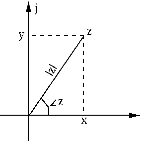
impedance is different from resistance: "complex resistance"
The result has both magnitude and phase: Phase with respect to the input sinewave. if Z = x+ j*w*y, then
 fourier.eng.hmc.edu
Take the Laplace transform of the relationship between current and voltage for a capacitor,
First order natural
HP and LP filters, with capacitors:
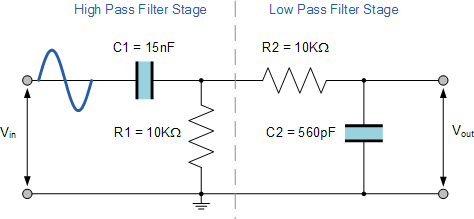
another version, bandpass, again a passive filter
 www.electronics-tutorials.ws
Below the
low pass VCVS second order filter with dependent voltage source--subject of
the Filter Quiz:
output = K*V+; (See Horowitz and Hill, chpt 5 handout, p. 273...)
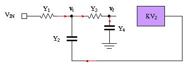
The red arrows are the current direction conventions, and by the node
admittance matrix method of the Resistance lecture current out is + and current
in is negative.
We could write down the node admittance matrix by inspection...except for the dependent source in violet...
KCL for the left node V1 is -(Vin - V1)*Y1 -(KV2 - V1)*Y2 + (V1-V2)*Y3 = 0
we end up with a break in symmetry in row 1, col 2 of the matrix:
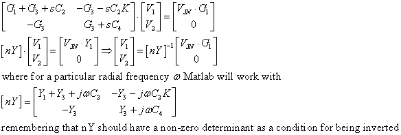
showing the method for dealing with a dependent source.
s = α + jω and phase: As a computational matter, in the equations above, the spectrum will be determined by letting s = jω0, where ω0 is particular frequency (in a Matlab for-loop). As a result, every response at a particular frequency is a complex number (see diagram above). Each complex number can be expressed as magnitude & phase and each component can be plotted separately as a function of frequency. The phase of the output is with respect to the sinusoidal input, implicit in any purely imaginary version of Laplace transform variable s.
The VCVS filter spectrum calculation will be completed in the Filters lecture, and exercised as a Matlab function in the Filter Quiz...
non-capacitor remark: Because capacitors are invariably used to design filters, and because filters are described by their spectrum (response vs input frequency) we take the space here to pause and remind you you have seen Fourier series before, and tell you understanding Fourier series will start you on your way to figuring out how to calculate a spectrum and understand the sampling theorem.
Truncated
Fourier Series of periodic function h(t)
(low pass filter eliminates higher frequencies...)
![]()
holds true for a periodic function...
Note the fundamental frequency in radians is = omeg0 = 2*pi/T where T is period.
How many unknowns are there? the a's and the b's... 20,
not counting a0, the mean of the periodic formula...
The calculus book formula for finding Fourier coefficients looks like...
s![]() solving another integral...
solving another integral...
but if we are recording/sampling waveform h(t), we don't know h(t) analytically.
What about 20 equations in 20 unknowns? samples spaced how far apart?
results in another matrix inversion problem... Wait for the lecture on the Sampling
Theorem...
Capacitors
as sensors:
If pressure can reduce "d" the thickness of the dielectric, then capacitance
can increase, and the capacitor becomes a pressure sensor. If some chemical
(for example water vapor for relative humidity) can change the relative permittivity,
then again a capacitor becomes a sensor.
Capacitance
of lipid bilayer in nerve cell membrane: 1
micro-farad / cm^2;
40 angstrom width of bilayer...
There's a huge electric field (volts/meter): 100mV/4*10^-10m = 25 x 10^8 volts/meter
implies one tough membrane...
Capacitors
vs batteries: The case of the super-capacitor:
Batteries
can store electrical energy--for example, from solar energy collectors for use
at night. However, batteries can take hours to charge up. A capacitor can store
energy, and charge up in msec. Compared to batteries, however, capacitors have
less energy storage density. Enter the super-capacitor, which uses chemistry
to store more charge, albeit still on surfaces -->more surface area, more
charge storage... see
battery: 3 amp-hours * 12 v implies 3*12 = 36 watts * 3600 sec = 129,600 Joules >> 1F*10000 volts = 10,000 J
Patrice Simon, Yury Gogotsi, Bruce Dunn, "Where Do Batteries End and Supercapacitors Begin?, Science 14 March 2014, Vol. 343, pp. 1210-1211.
for
a perspective on this topic.