LabVIEW and MAX
Learn more about LabVIEW from the documentation under the Help menu, the NI website, or the books in the lab. (Do not remove books from lab!) We are using LabVIEW 7.1. For 2013 we have 8 XP machines running 7.1. We are currently negotiating with National Instruments for an (affordable) license to upgrade LabVIEW for 123.
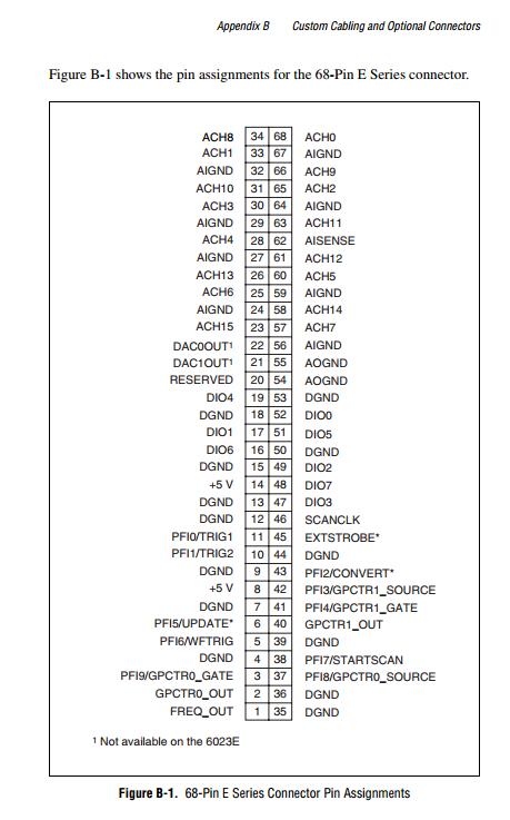
Associated with each setup is a 68 pin cable from the 6024E card to a green screw terminal card that allows you to hook up wires for input and output from the 6024E card... See bottom of page for pinout...
To read the LabVIEW Users Manual from the internet
go to
http://www.ni.com/pdf/manuals/320999e.pdf
It may take 30 seconds or so for the download, since you will be ending up with a several-hundred page book. You must have Acrobat on your computer for the book to come up on your screen!
The first "virtual instrument" (VI) concepts to appreciate about LabVIEW are the Front Panel and Block Diagram windows that are part of any VI. The front panel contains control knobs and indicators, including graphs; the block diagram uses a different pallette of functions and processes the inputs to generate the outputs... It has one section NI Instruments / Data Acquistion that contains icons for analog and digital input and output, for connection to outside sensors and actuators.
For Lab 0 you will want to read Chapter 8, Loop and Case Structures.
When you click on LabVIEW 7.1 on a computer in the lab, the first screen will have link to the Getting Started manual, which you may also scan with Acrobat.
With each lab setup there is a one book or another on LabVIEW (example: Bishop, from Univ Texas at Austin), which may help you get started.
MAX is the Measurement & Automation Explorer that can test the 6024E board independent of LabVIEW. (yellow arrow/blue bird icon), Click on "Devices and Interfaces". Click on "Traditional Devices". Highlight the 6024E entry and hold down the right mouse button.
To look at Analog IN for examples, First select Properties and under AI properties make sure "Single Ended Reference" is chosen for Analog IN. Go back to the right mouse button and select Test Panel. When the test panel comes up select Analog IN and the channel you are connected to. You should see it reading the voltage you are sending in. If not, something is wrong that you can troubleshoot or call the TA about. Do no leave Test Panel open while LabVIEW is running.
Practice with the Wiring Tool to become comfortable with hooking up icons. You can hit tab to switch between various tools.
Another recommended book: Bruce Mihura, LabVIEW for Data Acquisition, Prentice-Hall (2001)