Fan
Lab Addendum for pre-selected motors version... JDD
Nov 2018
Here you forego the mechanical
excitement of building your own trio of fans and circuitry for the Fan Lab.
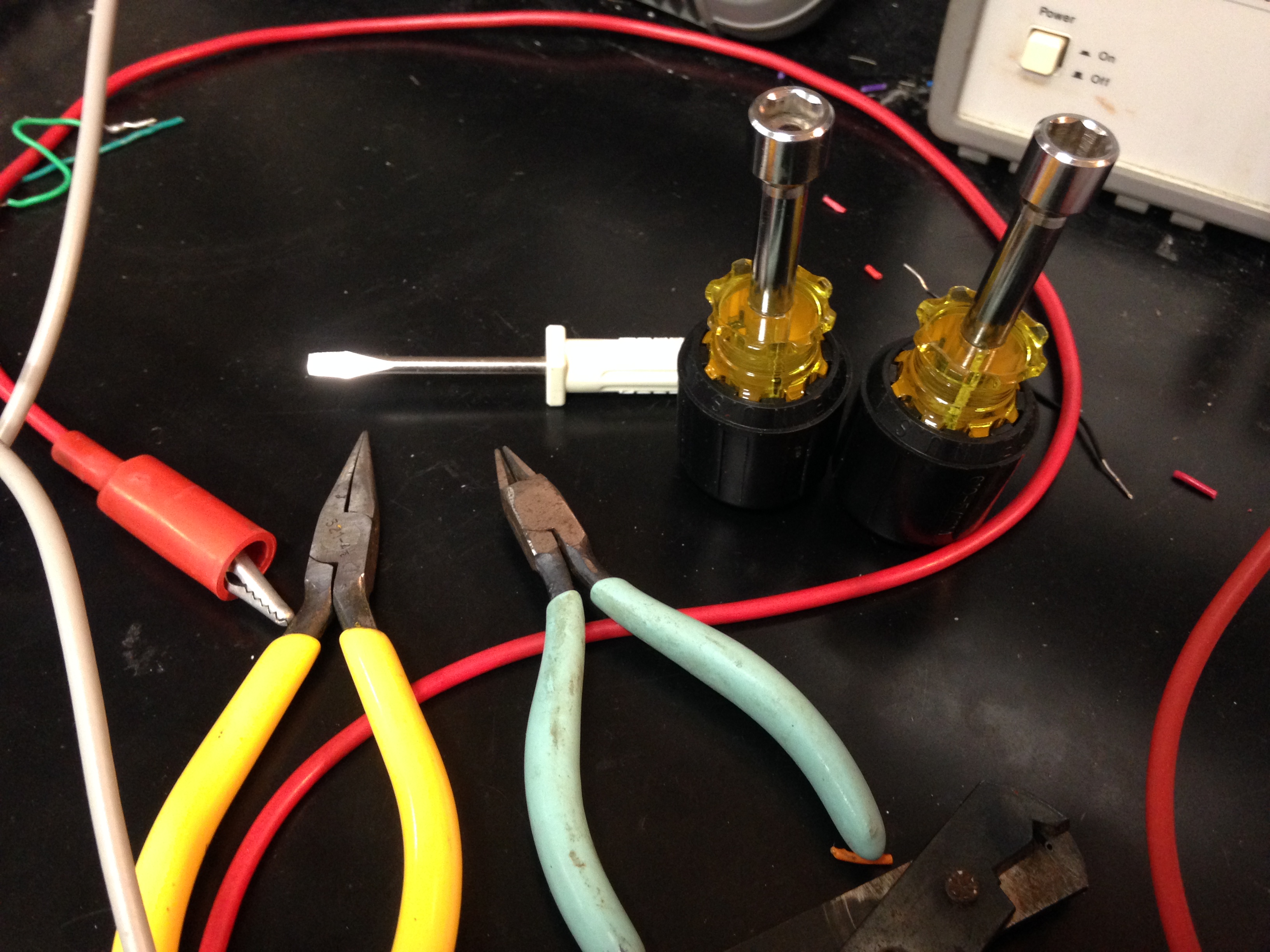
I have selected and tested 3 fans that are suitable for the Fan Lab requirements,
and have lashed them together with 8-32 threaded rod, and tightened the connections
with two nut drivers:
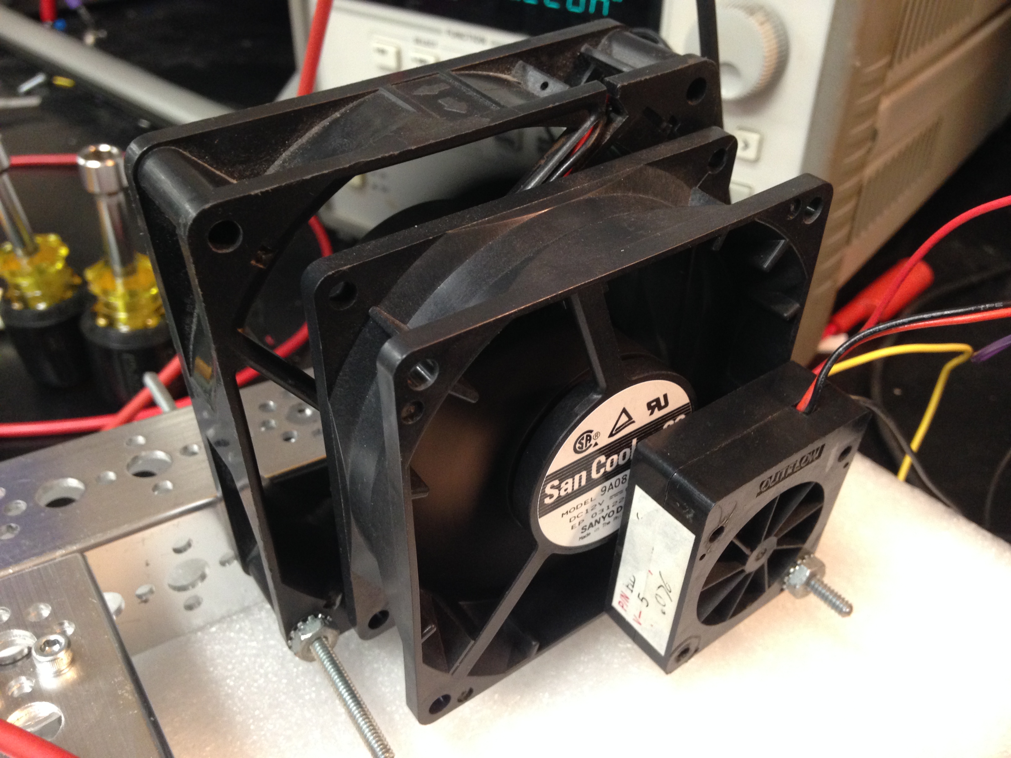
The Big Fan, at the rear of the stack, is manually controlled from the +25v supply on your 3631 triple output power supply.
The Middle Fan is controlled
via a signal from LabView DAC-ch-0. See schematic below:
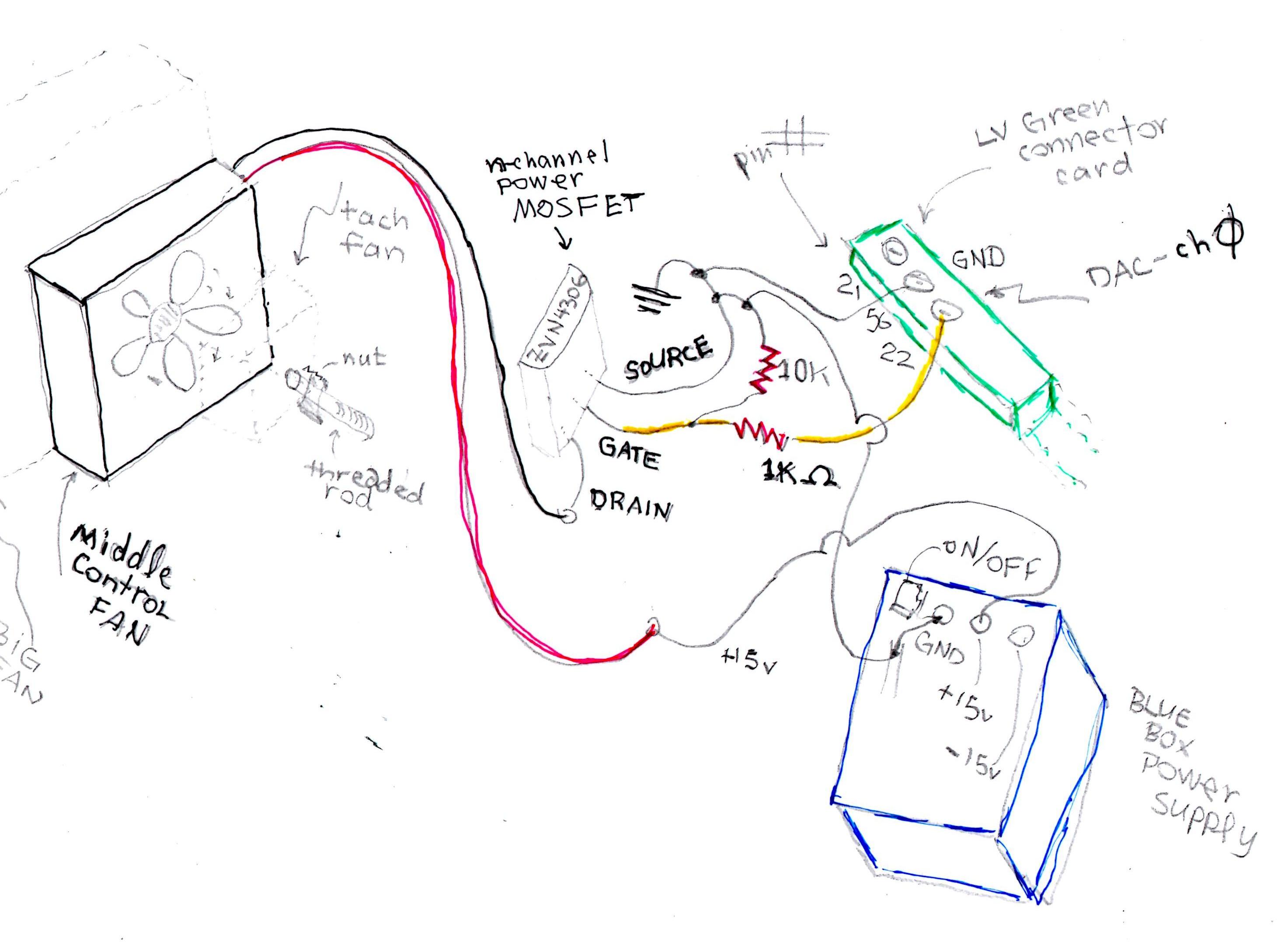
The gate of a n-channel power
MOSFET ZVN4306 receives the DAC out voltage and modulates the current flowing
from drain to source, thus controlling the air flow from the middle fan. The
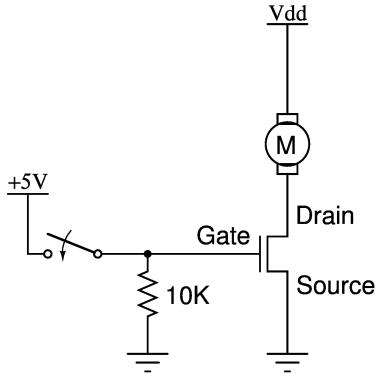
power for the MOSFET comes from a Blue Box power supply, with it's own +/- 15
volt supply. A more schematic version of such a circuit is shown below:
The yellow wire connection
from DAC-ch-0 is already set up. In fact, the only thing
you should touch in this setup, besides the keyboard/mouse of the computer where
you build your Fan Lab VI, is the knob for controlling the Big Fan voltage.
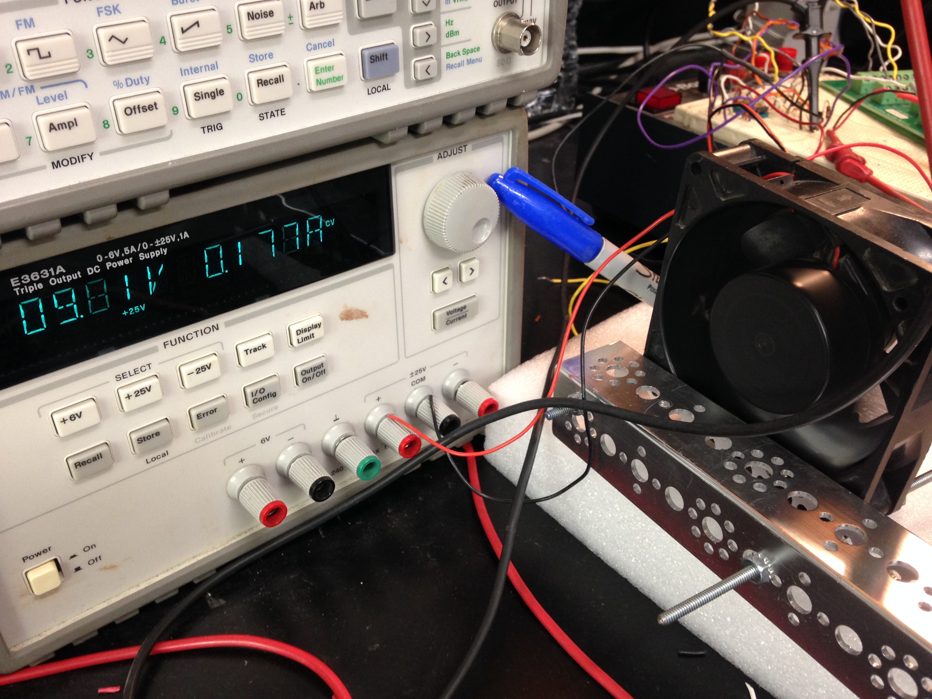
See blue sharpie leaning against the Big Fan adjust knob...
In particular--except for the Big Fan or LabView--don't turn off anything when you leave.
At any rate, if you think any of the components of the setup have truly failed, text me at 310 600 0425 and I will journey to 097 ASAP.
If you find the above request too restrictive, I invite you to NOT forego the mechanical excitement of building your own trio of fans plus circuitry.
The two output wires of the passive sensor tachometer fan go to pins 1(red) and 2(black) of a 524 set for gain of 100, a circuit you have built before and need no schematic to understand. The 524 output goes to Analog-In Ch-11 on the green connector card.
OK, here it is anyway: for gain of 10...not shown is +/- 15 volts to pins 7 and 8.
In a perfect world, when you first sit down with the "pre-selected" setup, you will be shown the front panel of a VI that demonstrates a proportional control solution that is satisfactory for getting checked off, but could be improved upon. The "solution" being a negative feedback proportional control system that keeps the output of the tach near a desired level in spite of the TA increasing then decreasing the Big Fan voltage by 10%.
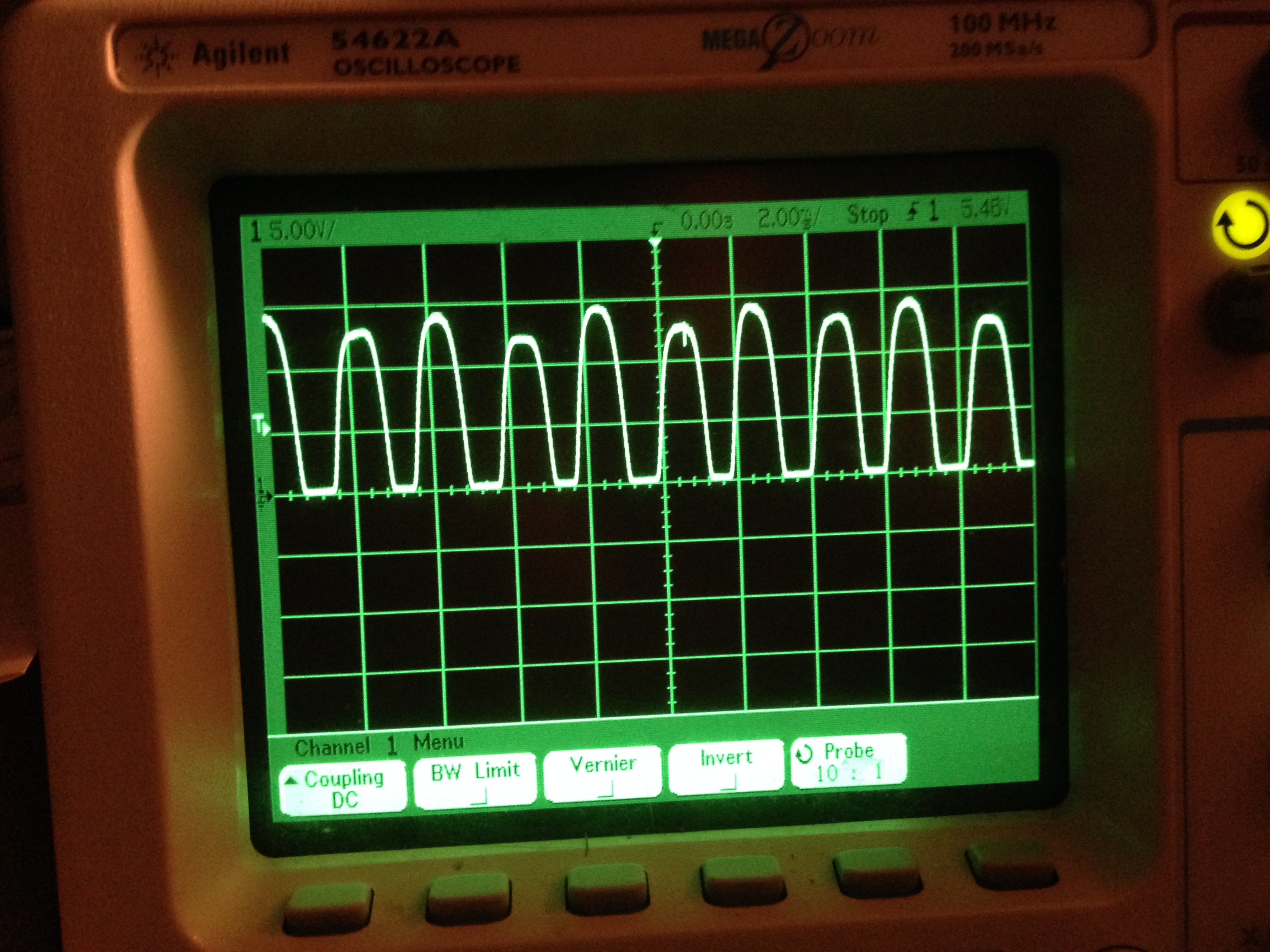
At this
point let me tell you that the output of the tach is an "AC" signal
looking like the scope face shown below.
For your VI and its handling of the Ain-Ch11 RSE signal, I urge you find the LabView example of "Moving Average" and for a reasonable sample start with a 25 point history and the output of the tach. You will have seen such a result in the demo...which has now disappeared from you, in your need to start your VI from scratch. Have the moving average (in a continuous running VI) be on a chart waveform (as it is in the LV example...) and a indicator on your front panel.
You will have been shown in the demo that if you have your Big Fan voltage at 11v and the middle fan is off, there is virtually no output from the tach.
Now in your new VI use DAQ Assist to create a DAC ch0 control for the middle fan. It will be helpful to limit the max voltage to about 8v.
You should explore the range of DAC-out voltages going to the MOSFET which cause changes in running average tach fan reading; you're likely to find that at Big Fan of 10 volts, the thresold for middle fan response is about 2v and the saturation response is somewhat above 3v. Therefore explore to the nearest 0.1 volts in that range for your equilibrium setting.
You are now ready to find a reasonable equilibrium point: Your equilibrium point will be a combination of Big Fan voltage and Middle Fan Aout such that if the Big Fan voltage changes by +/- 10% then your feedback system will compensate to return the tach to about the equilibrium output.
Hint:
Appreciate that you want the middle fan to have significant influence over the big fan. Contemplate what that means for an optimal Big Fan equilibrium setting...
You should also feel free to adjust the "history" of the running average: too little and there's too much AC in the tach representation; too long, and too much delay in the system...
Once you have found such a equilibrium and you call over a TA for her to check you off, the first thing the she will ask is for you to set your feedback gain to zero so your system is "open loop." She will then move the Big Fan voltage up and down and determine that--yes--your tach output does deviate from the desired equilibrium. She will then have you turn up the feedback and see if your tach output stays reasonably close to its equilibrium value. If so, congratulations!
Yes you can get extra credit for bang-bang or integral compensation, but that is frosting on the cake.