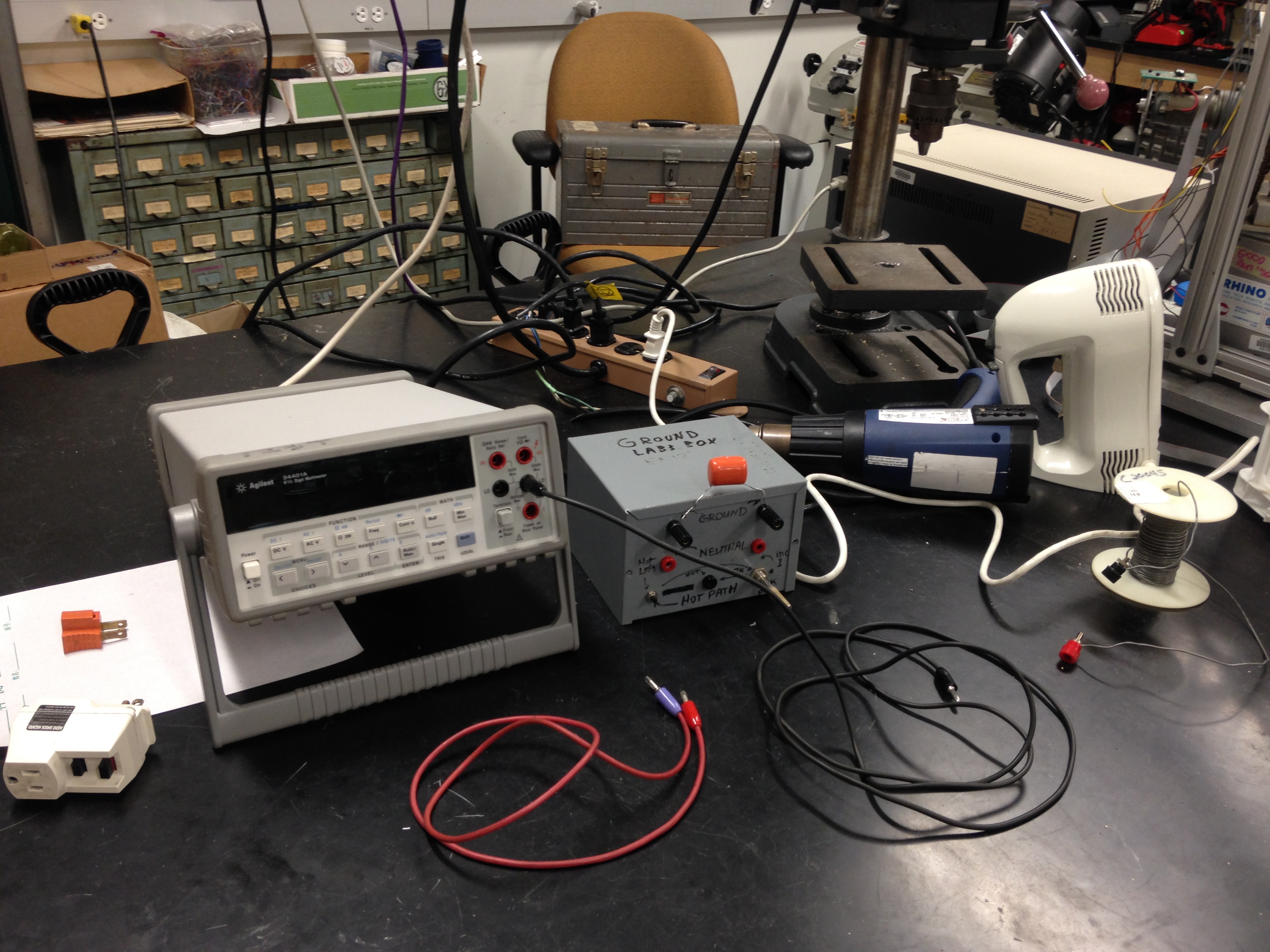
FIG 1
You will want to return Lab 3 to this appearance after you finish with your measurements...
Lab
3: Update, Sept, 2018, for rm 097
Ground, Ground Loops, and Ground Fault Interruption
Background:
A 3-prong power
outlet has slots for Hot, Neutral and Ground (Black, White, Green).
Hot and Neutral carry current to and from the load, be the load a light bulb,
power supply or motor.
Ground should carry no current.
Ground is there for safety reasons, for shielding, and for a stable voltage
reference.
In this lab you will look at ground vs neutral, induced voltages in loops of ground wire, and how a circuit can detect a leakage current fault on the ground wire, and open-circuit the hot path as a result. (GFI)
Overview of rm 097 Setup:
FIG 1
You will want to return Lab 3 to this appearance after you finish with your
measurements...
From left to right, you
have
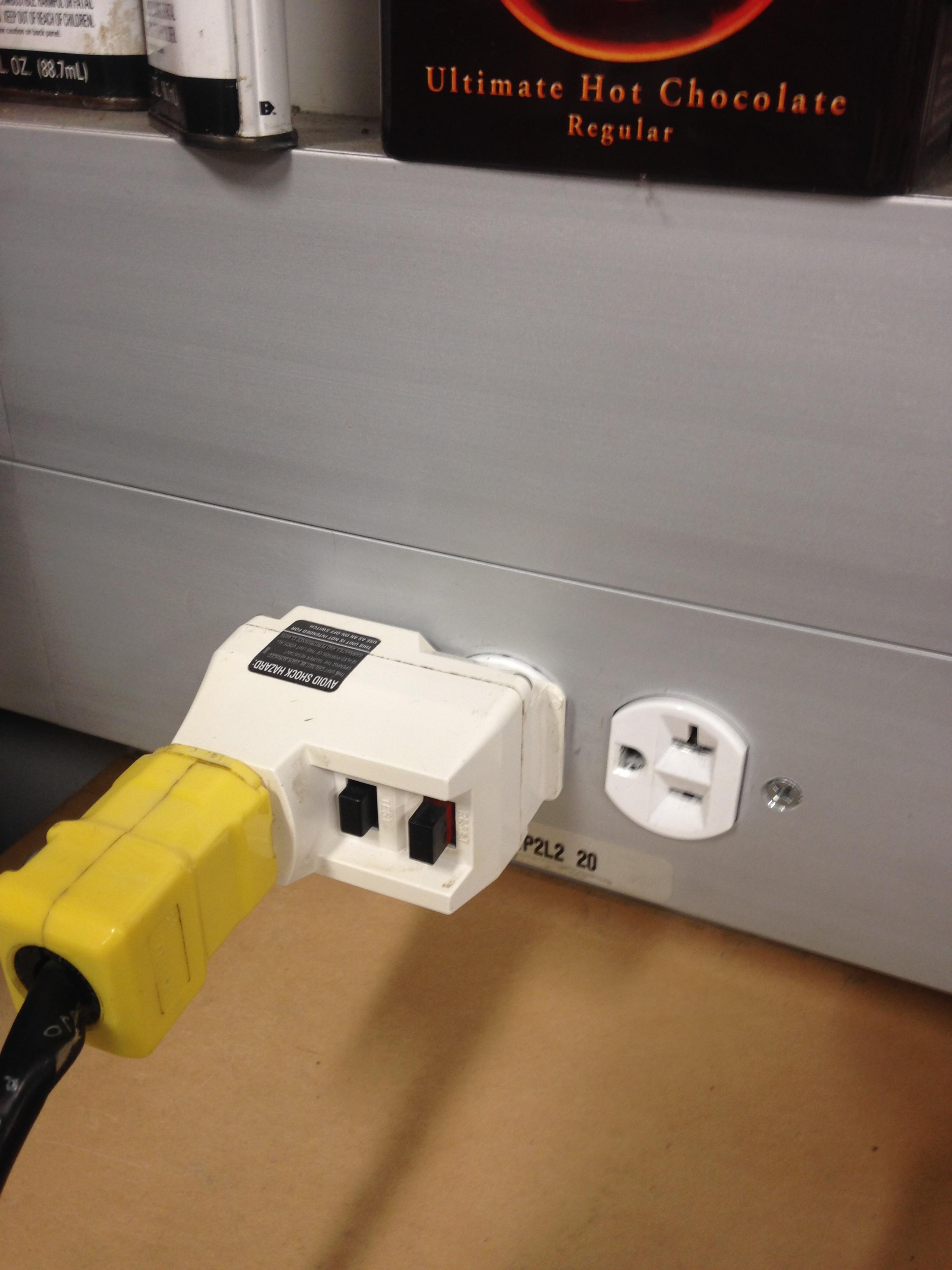
Orange cheater 2 prong plug
White GFI
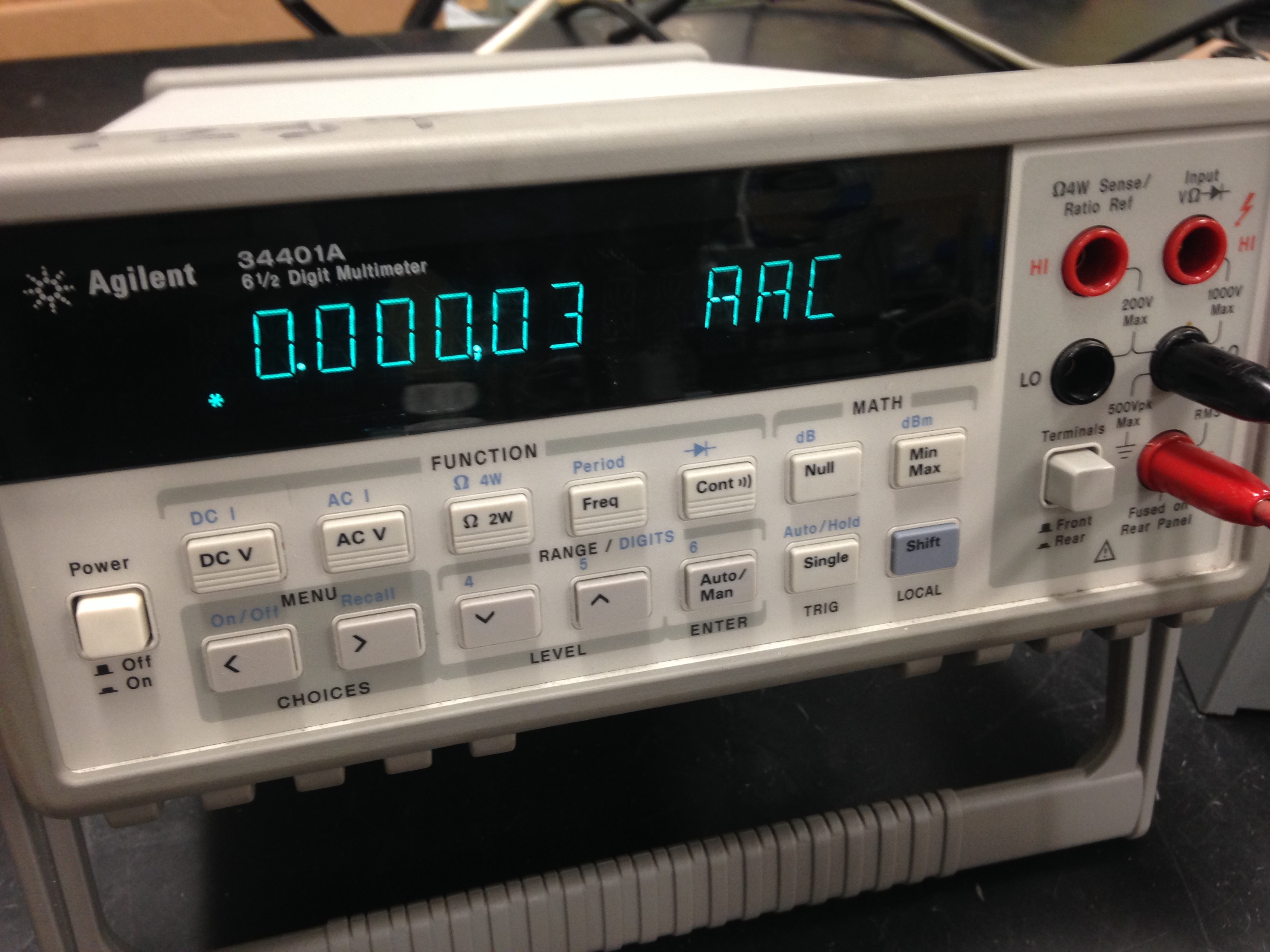
Agilent DMM (use the double banana cables--red and black--for connecting to
the DMM)
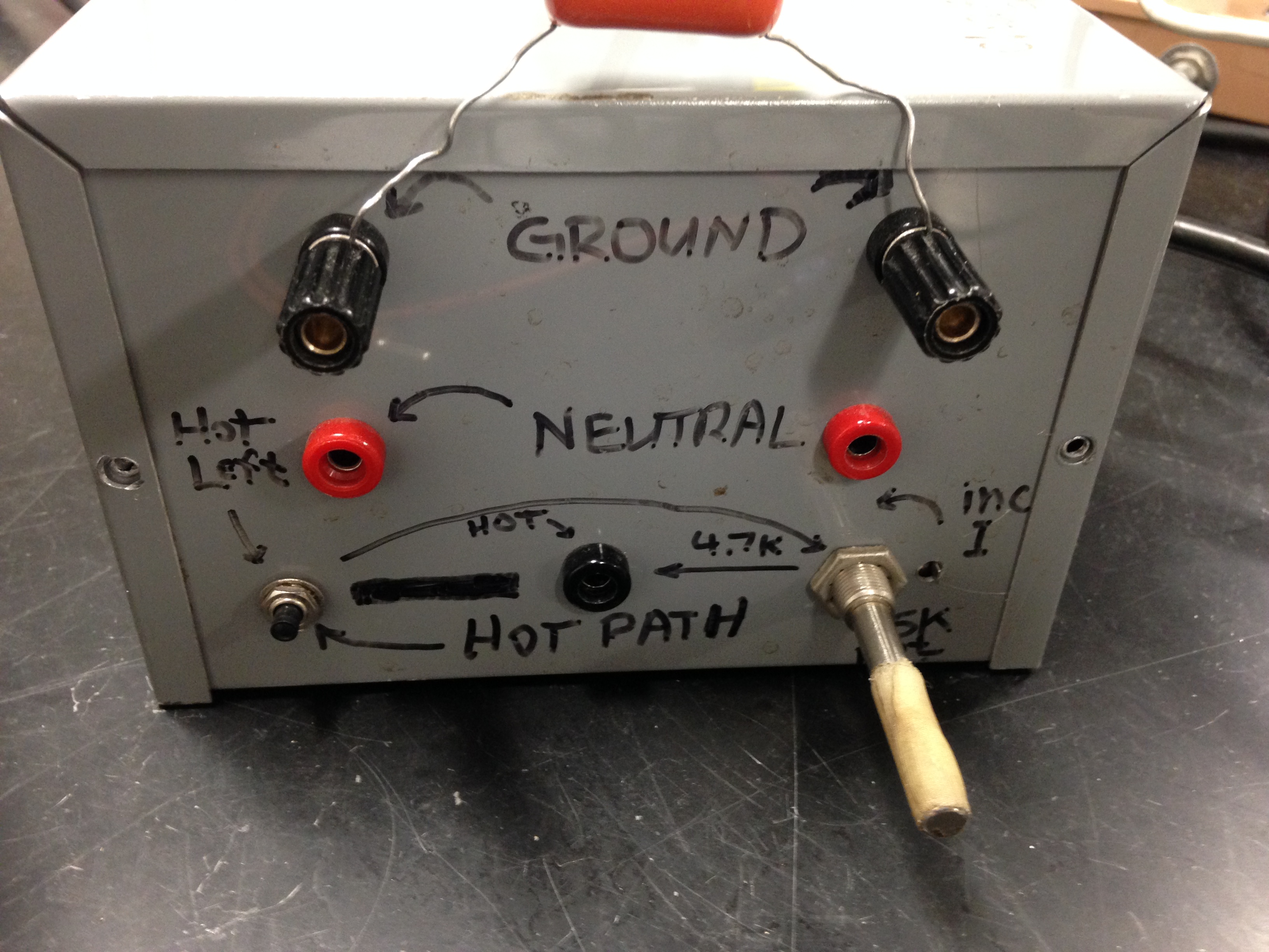
Lab 3 break-out box for two sets of Hot Neutral and Ground
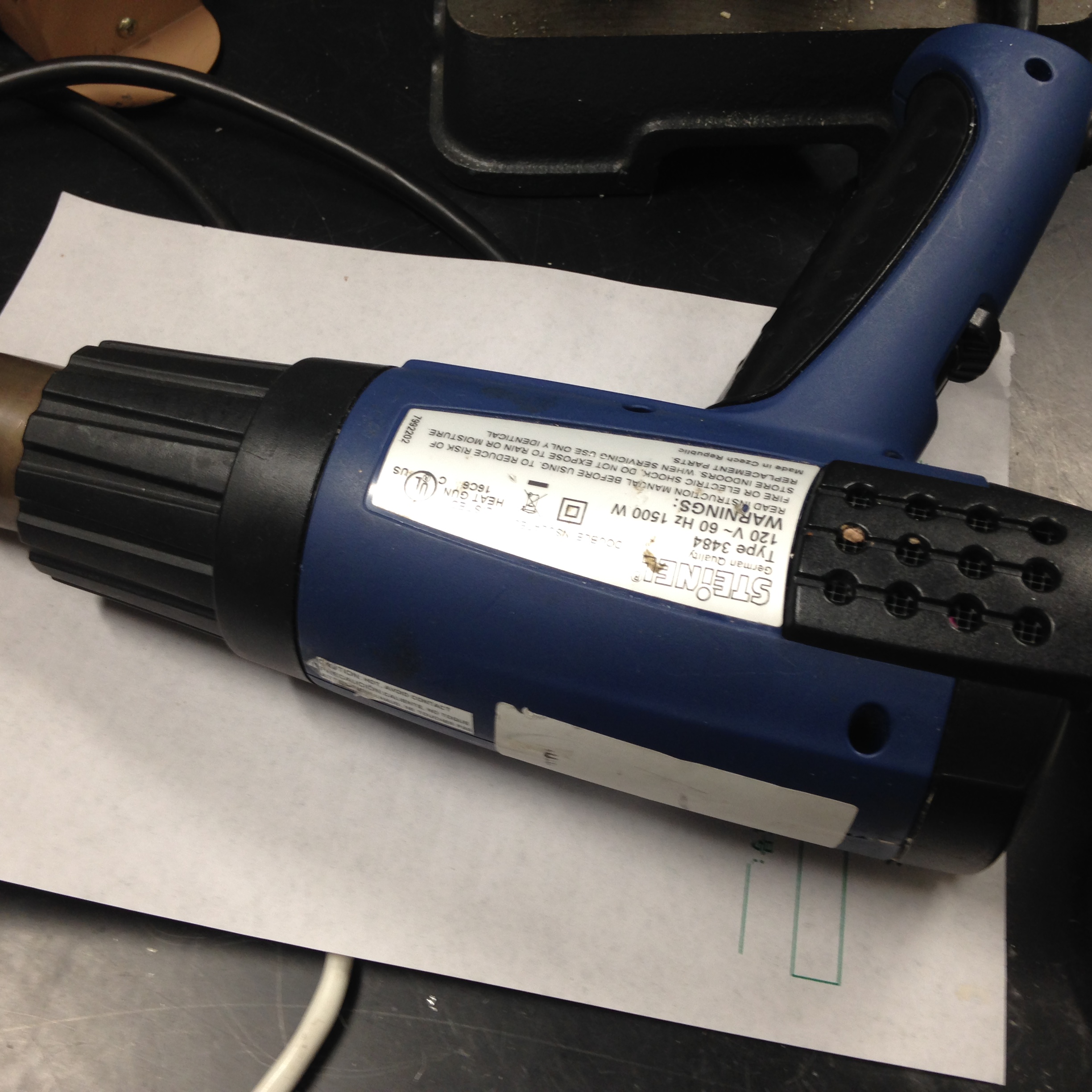
Heat gun
Electric mixer for generating magnetic fields with it motor
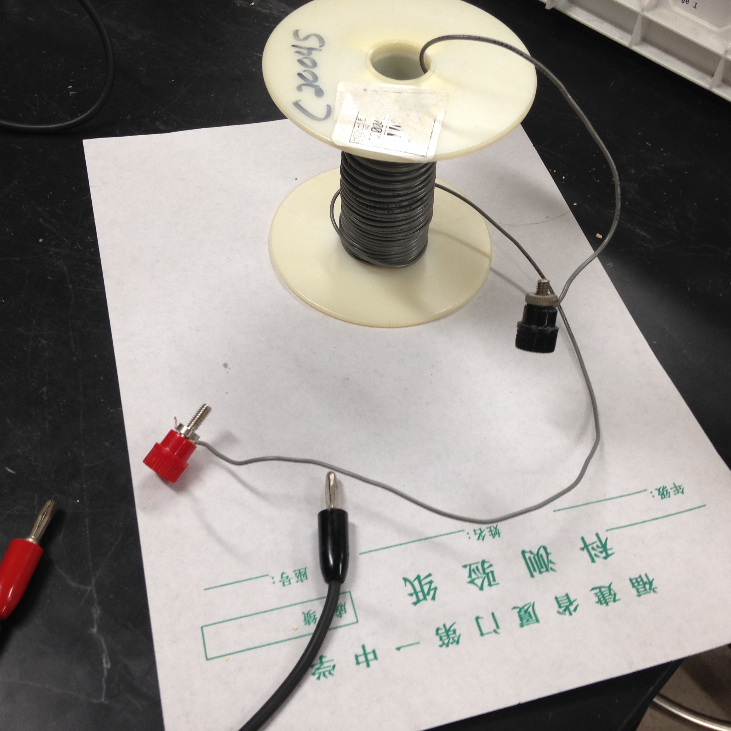
Spool of gray wire in the form of a many-winds of coil, with female banana plugs
on the ends
In front, banana cables
In the middle on the table is a plugstrip where the right-side power cord of
the breakout box is plugged.
A drill press is plugged into the same strip for drawing more AC current through
Neutral return; so too is a heat gun.
On the south wall in the upper left corner of Fig 1 the left side power cord
of the breakout box is plugged into a different strip.
Requirements:
1. Plug in the bananas for AC Volts in the DMM into the right side of the box,
for GND and Neutral. Measure and record the voltage difference between Neutral
and ground. At the point where electricity comes into the building Neutral and
Ground are welded together. Why is there any voltage difference between GND
and Neut when the separate wires reach 097?
1B. Turn on the drill press
and record what, if anything, is different about the Neut-to-Gnd AC voltage
reading.
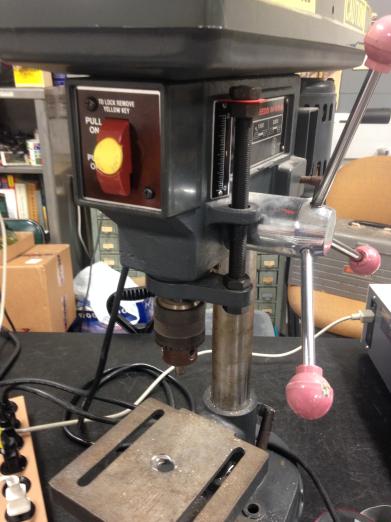
If your TA has super-powers and can hold the chuck of the drill press still
while the press is on, then record any further difference in reading. For even
more change, turn off the drill press and turn on the 1500W heat gun...
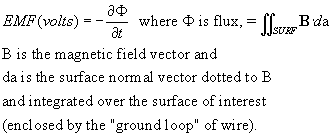
(2) Example of Faraday's Law: Ground loop voltage due to AC magnetic field...
See this equation for a review of Faraday's
Law.
Place the banana leads across the two ground outlets on the breakout box.
You will have formed a ground
loop with a voltmeter in series. The ground loop extends from one connection
of the DMM to the Left ground lead on the south wall and around through the
box, and out to the table plug strip.
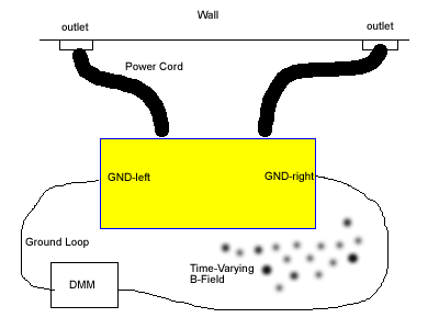
2. What is the voltage across the 2 grounds? (we hope it is less than one millivolt!) Record your answer. You may want to connect a 1µF "orange drop" capacitor across the ground binding posts to filter out any non-60Hz noise that may be contributing to the AC voltage...
2B. Turn on the mixer. Move the mixer, and its magnetic field, near the surface of the ground loop, inside and out, knowing that the 60Hz-changing B field is a vector with 3D of x, y, and z, and rotational aspects of roll, pitch and yaw. Search for the mixer position that gives the greatest increase in AC voltage from the ground loop. The TA may try to beat your maximum reading...
2B. (optional) Connect the
two ends of the coil of gray wire across the two bananas going into the DMM.
Move the coil around a stationary mixer to see how the the coil-to-voltmeter
circuit might be used as a detector of (changing) magnetic field.
(3)
Plug the LEFT side of the breakout box socket into the WHITE GFI outlet plugged
into the south wall receptacle.
The button on the right of the WHITE GFI is RESET: press RESET after every time
you plug it in or after you hear it click on detection of a ground fault.
Press the RESET switch on the GFI. On the breakout box is a pushbutton switch
that will route HOT through a 75K Ohm potentiometer in series with a 4.7K fixed
resistor. The other end of the resistor connects to a banana outlet on the front
of box.
Place
your DMM in AC current mode, in series with the HOT female banana, to LEFT ground.
To measure the current in the ground fault. You will need to put one lead in
the lower red banana socket so the current is routed through the proper path
in the DMM. See the red banana coming in at the socket below:
On
the front panel of the box hold down the pushbutton on the left, turn the potentiometer
knob CCW to increase the ground fault current until you hear a click/pop when
the GFI mechanically disengages the hot wire. How much current was flowing to
ground when the GFI activated? Write down the answer in mA.
Press the RESET button on the GFI to repeat.
(Optional)
What happens if you turn on the 2A drill press while the ground fault current
is increasing?
What
happens if you plug the GFI outlet into a 2-prong "cheater"? Can you
see any ground fault current?
Remember
to take the current lead OUT at the end of the GFI experiment, or the next person
may try to measure voltage and blow a tiny fuse in the current detection path
of the DMM.
Passing on to the FTQ of Lab 3 requires reasonable
answers to
* Neutral-to-Ground AC voltage
* Maximum increase of AC voltage from changing magnetic field near a ground
loop
* Minimum AC current needed to trip your GFI
Once you're ready for the FTQ about a GFI, take a minute and return the Lab 3 area to approximately what you see in Fig 1.
FTQ:
1. Explain (in a private version of public speaking...) how a typical GFI
circuit works.
See script for latest version
of a good "elevator speech."
Reading: Read chapter 14--by Olson--of the Webster book.