Lab
4B: Driving While Lit Up: Guiding a RC car by telemetry from a beacon over a goal
Background: In
Lab 4 you learned to send out control signals to the Mayhem RC Car from LabVIEW
to navigate "ballistically" to a goal on the floor. You were able
to set the initial position and orientation of the car to insure success. Here
in Lab 4B we will vary the initial orientation and distance from its goal of
your car. The goal will be underneath a bright halogen light 3-6 meters away,
30 cm above the floor.
The car will be able to
determine the direction of the light with phototransistors on its front, arranged
like you had in Lab 0.5. The phototransistor signals will be A-D converted on
the car, then encoded from UHF transmission up to a radioreceiver near the computer.
The received signal will be decoded and re-established as 2 analog signals for
contact with the LabVIEW green connection board.
Requirements:
Arranged on the
green connector card:
ACH6 ACH7 are the A-to-D-to-A phototransistor signals to 4 bits of resolution.
ACH4 is the goal signal from the scoring circuit.
ACH1 is the
The phototransistor circuit
below resides on
your RC car, physically set to aim in the car's forward direction.
The "totem pole" will be powered by the 9.6v battery on the car
and the PN-150 phototransistors are the same ones you used in lab 2.
 graphic
by Jon Halperin
graphic
by Jon Halperin
You may not need the resistor
to ground in the circuit above.
You can if you wish, use ONE phototransistor aimed in the direction of vehicle
movement.
With one photoxsistor only, the response will tail off in either direction from
optimal,
instead of the preferred direction being along a monotonic pulse rate change.
Vout of the phototransistor
circuit projects to the input of a AD654 voltage-to-frequency converter
(voltage-controlled oscillator, VCO). See diagram below and go to the Analog
Devices website
for the data sheet of the chip. Note that the open collector output resistor
of the VCO (pin 1)
is pulled up to 3.3 volts, the power supply voltage required on the UHF transmitter.

Use the TI TSP7333 voltage regulator (DIP chip) to supply the pullup voltage
and the power supply voltage to the UHF transmitter on the vehicle.
(For pinout and more data on
this chip go to the TI
website.)
The base frequency of the 654 should be around 1000 Hz; it is a function of
the
external resistor and capacitor connected to the chip.
You should verify that rotating
the phototransistors in front of a light
causes the totem pole output to vary, and that the variable phototransistor
output
causes the frequency of the VCO to change. You will also notice that the
output of
the phototransistor-pair will vary as a function of distance from the halogen
light.
Next, send the output of the
VCO to the data input of a LINX UHF transmitter,
which will also be powered by 3.3 v and will ride along on the car.
The frequency of the transmitter and its receiver will be either 318 or 415
MHz.
You will be given a transmitter receiver pair with wires already soldered to
their pads,
with a temperature-controlled soldering iron.
The pair will have been tested and you should have no problem with
you UHF link if you wire up the pins to your breadboards properly.
Go to the LINX
website to see the pinouts of transmitter and receiver chips.
See below the first page of the downloaded transmitter datasheet:

The receiver will be near
the LabVIEW green connector card, and will be powered
by another 3.3v regulator. Test with your oscilloscope whether the pulses
sent to the receiver appear on the data output pin of the receiver.
The receiver output ("data") is not a true logic pulse, so it should
be "clean up"
by passing it through a TTL logic chip. See diagram below.

Now you're ready to have LabVIEW read the pulse rate.
On the Data Acquisition menu, under Counters, you'll see a FREQ icon.
FREQ counts logic-level pulses on the GATE input; for counter 0 the gate input
of the 6024E is pin 37. Don't forget to ground the green connector card at a
digital-ground, too. See diagram below for a VI that tests the FREQ icon.
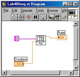 A reasonable value
for Duration would be 1-2 seconds...
A reasonable value
for Duration would be 1-2 seconds...
Run the VI above on "continuous" (two arrows tail-to-head) to watch
the rate change as
you move the car around near the light. Try turning off the overhead lights
for better
signal to noise ratio. Once you can read the pulse code from the on-board sensor,
imbed
it in a program that controls rotation and translation of the car (extension
of Lab 4).
Testing your sensory-guided
controller: We will
orient your car plus or minus 30 degrees
3-4 meters from the halogen light goal. The 3-4 meter distance will be on a
line in the
direction the light is shining. Thus both initial angle and distance will be
varied.
Without further intervention in the program from you, once your VI is
started it should
guide the car to pass within +/- 1 foot of the (projection on the floor of)
the goal light.
There is no particular time limit, but let's hope the attempt is over in less
than 60 sec.
By the 50% rule, if your car can reach the goal 50% of the time from random
starting
positions, you will meet specs.
Free Advice : Your main problem may be dealing with the combined influence
of orientation to and distance from
the halogen light. You may want to collect a significant amount of data on the
response of the phototransistor system
at various angles and distances, in order to craft your algorithm for guided
movement.