Lab4
λ
18: Reading Phototransistors on ADC Inputs to Arduino:
Background: Here you will send the two DAC output channels on the 6024E card to analog-in's on the Lab 4 Arduino board. The analog signals will simulate the output of two phototransistors (photox). It will be imagined that the phototransistors are responding to a distant light source, as they did in Lab 2. Based on the sum and difference of the two analog signals, the code will orient the (simulated) rover to point toward the light. In essence, the phototransistor signals will act as FEEDBACK for navigating the rover to turn off a switch under superbright LED on a "clay pigeon" rover.
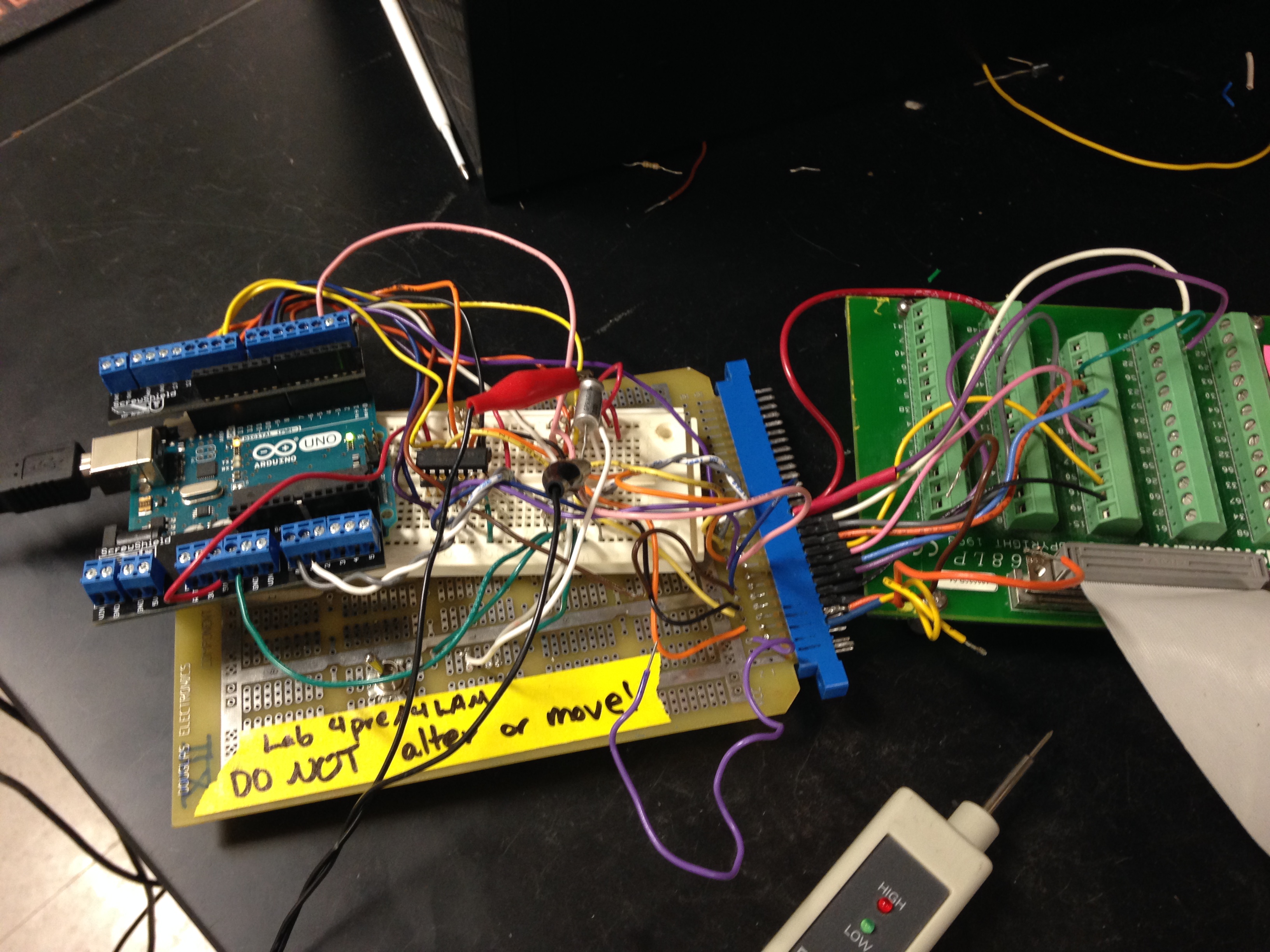
Notice that the Lab 4 green NI connector
card has ADC output pins 21 and 22 (violet & white wires) going to the Arduino
card, to analog-in pins (grey & white wires).
Re: the image above: You will do Lab 4Pre and Lab4Lam with an Arduino card and NI 68 pin connector wired together. The Arduino card will have a USB A-B cable connecting it to the desktop computer, for your code upload and for power to the Arduino. There is no need for you to adjust or change the wiring. Your only reason for handling the setup rig might be for you to plug the 68 pin flat ribbon cable into the NI green card. A default VI and Arduino code (read-only) will be running to prove the connections and switches and LEDs all function as expected before you begin modifying your code. There is no reason for you to move the rig (one of three in the labs) to another computer...
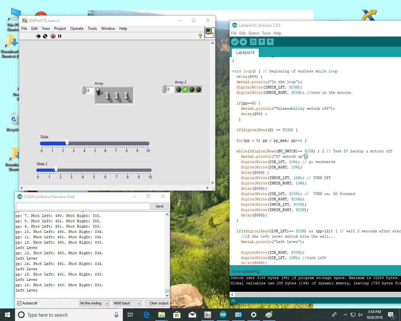
The demo
running when you first encounter 4Lam is on JDD's account, so you will have
to log out, log in on your account, use your switch-LED-slider VI, and rename
Arduino default for your team. Below is a full screen shot of the demo code
in action. Previous to the screen shot the VI was turn on "continuous,"
then switch D6 was flicked up and down to start the Arduino code, then switch
D4 was moved up (representing the left wall) and LED 2 turned on in the demo
code representing the right wheel reversing. Below the front panel you can see
that the Serial Monitor of Arduino code was turned on, and "Left Lever"
was printed out; also, the photox's are seen to be functioning properly in the
code...with slider values proportional to "Phot Left" & Phot Rght"
values printed out.
If, perchance, you are starting Lab 4Pre and are unable to get 4Pre to look
like the above, and have tried for 15 minutes, then consult a TA. If, after
another 15 minutes you are still unsatisfied, TEXT JDD-- 310 600 0425 --and
he will make things right ASAP.
At any rate,
if you're on the beam, Upgrade
your Lab4pre VI to generate 2 analog-outs, controlled by sliders; the
sliders will have a range of 0-3 or 5 volts: your Arduino card analog inputs
can handle up to 4.8v.
Have the LEDs L0 to L3 represent what they did in Lab4pre:
L0 LOW left wheel going forward
L1 LOW right wheel going forward
L2 LOW left motor turned ON
L3 LOW right motor turned ON
The switches
D4-D7 act the same as they did in Lab4pre:
D4 ON implies rover is in contact with left wall
D5 ON implies rover is in contact with right wall
D6 flicked ON means the timed pp loop is activated inside the infinite void
loop( ).
D7 ON still causes simulated rover to back up.
Now to get going on 4&Lambda:
First, declare in Setup:
int photoL, photoR, thet_diff_LO, thet_diff_HI, thet_summ_LO,
thet_summ_HI;
signed int diff, summ;
These lines declare variables for the A-D conversion.
We suggest you compute:
diff = photoL
- photoR; // difference of photoxsistors
summ = photoL + photoR; // sum of photoxsistors
Threshold values for thet_diff_LO
and thet_diff_HI should be smaller than thet_summ_LO, so you can demo failure
of the thet_diff's if the photox values sums are too low.
thet_diff_LO
thet_diff_HI
thet_summ_LO
thet_summ_HI
You may want to run the slider at 1v, 2v, 3v, 4v to see
how those voltages are represented inside Arduino, looking at the default serial
monitor...
FYI: You see
the following connections of LabVIEW connector card to socket/Arduino demo board:
DAC-OUT-0 screw 22 to
blue socket pin 25 (13) to Arduino ANALOG pin 0 Left
phototransistor/slider
DAC-OUT-1 screw 21 to blue
socket pin 27 (14) to Arduino ANALOG pin 1 Right phototransistor/slider
Green GND wire of blue socket to pin 53 (GND) of the
LabVIEW connector card.
----------------- ------------------ -----------------
Modify the renamed Arduino code to meet the specs of 4 λ
(3) Modify code inside
your pp < pp_max timing loop such that (in pseudocode):
(i) If summ < thet_summ_LO
then
the simulator behaves just as it did for Lab4pre:
goes forward by default or turns when it hits a wall or senses photox...
(this is the state of being too far away from the light source to care...)
(ii) If summ > thet_summ_LO
&& summ <thet_summ_HI
then
(iii) if diff < thet_diff_LO
(a negative number) then
(iv) turn CW (by turning OFF a motor) until diff
> thet_diff_LO
&& diff
< thet_diff_HI
ELSE
(v)
If diff >thet_diff_HI
then
(vi) turn CCW (by turning OFF other motor) until diff
> thet_diff_LO
&& diff
< thet_diff_HI
ELSE
(vii)
then go forward toward the light
(viii) if summ > thet_summ_HI
simulator
behaves just as it did for Lab4pre
going forward unless it hits a wall or sees photox...
(state of being too close to the light to make proper judgement...)
----------
----------------- ------------- --------------
Coding suggestions: As you make coding improvements, frequently "Verify." After partial success rename your code My4LamB, C, etc.
Possible
Testing of your 4 λ
. We'll see that one slider is labelled L and the other R. We'll leave all switches
down after flicking D6. We will run both sliders down to 0, then while the rover
is going forward we'll bring one slider (L) up until the "same" wheel
reverses. We'll then bring the other slider (R) up until it's near L and the
rover goes forward. Then continue to increase R until the R wheel reverses.
We'll then run L up until it's larger than R and the L wheel reverses. Next
we move R all the way to the max limit. As we then move L up, the rover will
go forward at a point sooner than the diff which causes different wheel direction
in the middle range.
Possible FTQ: Explain how the Arduino microproccesor converts analog
values for continued testing in the logic for the sum and difference decisions.