Your goal: You want to program a MSP430 microcomputer to "stand alone" on a roverbot, reading sensory and wireless signals, and sending out digital controls for stepping motors. To begin with, you have an evaluation board and a cable system connecting the evaluation board to the parallel (printer) port of a computer. Your computer is loaded with IAR software, that can edit and compile C code to be downloaded to the MSP430 chip. The cable will supply the chip with power while you download and study your code, perhaps by single-stepping in the DEBUG mode of IAR 2.5.
Putting the chip in the socket. Make sure the evaluation board has a computer chip, properly oriented, in its spring-loaded socket. The indent on the 28 pin chip is next to pin 1. Pin 1 is labeled on the PC board. Push your thumb down on the lip of the socket to open it up, place the chip, label up, then release the lip and make sure the chip stays firmly in place. You want a msp430F1232 chip in the socket. The msp430F1232 chip uses 10-bit successive approximation A-D conversion, compared to the msp430F123 (no 2 on the end) which uses dual-slope A-D. About half the MSP430 chips floating around the lab are 123's. We don't want them in the socket since we will be using the A-D feature of the 1232's.
Pinout of the MSP430F1232. Go to http://focus.ti.com/lit/ds/symlink/msp430f1232.pdf and look at page 3 to see which pins are assigned to what task on the chip. The rest of the 44 page document has details about what the chip does. On page 4, in particular, you can see the functional architecture of the chip.
The blinking LED demo. You want to double-click on the "IAR Embedded Workbench" desktop icon (with the green handled screwdriver pixels). From the File Menu create New:Workspace. Name it something like BlinkenLicht and save it in your team's IP folder. You can read about what you're going to do by navigating through the Start:Programs path to IAR Systems to the MSP-FET430 User's Guide (pdf). Check out page 1-4, "Flash"ing the LED. Note that FET stands for Flash Emulation Tool, where Flash refers to a type of writeable semiconductor memory onboard the MSP430F1232 chip. Next, under the Projects menu Create New Project; in the box you can use the same name as the Workspace if you like.
Next navigate to C:\Program Files\IAR Systems\Embedded Workbench 3.2\430\FET_examples\fet120\C-source for file fet120_1.c and make a copy in a folder in My Documents called IARstuff. Rename the file something like My120Blink.c. Under Properties of the file remove the Read-only restriction. You will be doing this transfer/rename so you don't link to the distribution software, and alter the code that must remain unmodified for other students to use.
From inside the IAR software, from the Projects:Add File menu, go to the IARstuff folder and and add My120Blink.c to your project.
Go to Projects:Options. Highlight (on the left) General. Make sure the Target tab is forward. From the Devices pull-down menu you should select msp430F1232. Next go to the C-Spy category (bottom on the left). Under Driver make sure the box says Flash Emulation Tool, and that in the bottom box it says "$TOOLKIT_DIR$\config\msp430F1232.ddf". Hit OK.
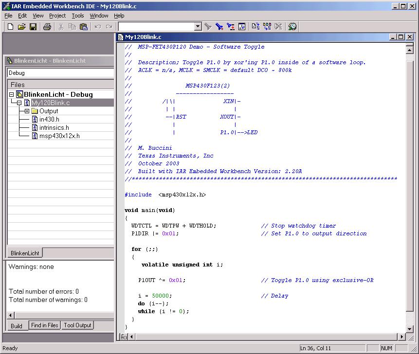
From Projects click on Rebuild All. If extend the Project tree you can see your
source code in a list. Click on the C source code: the screen will look something
like the image below:
Now under Projects click on Debug. For a second or so you will see flash by "Erasing Main Memory" and "Downloading Application" messages. You will be in the Debug mode. From the Debug menu click on Go. Look at your board. Is the yellow LED blinking about once per second? If so, Congratulations! (If not, double check what you've done, and if you still can't find an error, call over JD or the TA for troubleshooting. Who knows, you may have one of several defective MPP430 chips in the lab...)
Stop debugging. If you hit the "red hand" while the program is running the program will stop and the LED will quit blinking; if you go to the Debug menu and click on Stop Debugging you will return to the Editing mode. (If you click on Stop Debugging while the program will save in flash memory and keep running, the LED will keep blinking; in fact it will keep blinking even if you quit IAR...)
Editing the C source code. Return to the editing mode, for your source code. Change the green number 50000 to 10000. Click on Rebuild All, then Debug. Hit Go in the Debug menu and you should see the light blinking about 5x faster.
Running without the computer cable connection to the Emulation
Board. What you really want is for the board to
from the battery on the rover, with 12v from the battery sent through a 3.3v regulator
by way of a 7805 5v reg. An intermediate state would be running off 3.3v from the
Agilent supply in the lab. Each Evaluation Board should have two wires (red, green)
soldered to its Vcc and GND connector, for attachment to external power. First try
the Agilent. When you power up the board from an external supply, its yellow LED
should start blinking immediately. The TPS7333Q from TI is the 3.3v regulator
you will use. http://focus.ti.com/lit/ds/symlink/tps7333.pdf
Likely you drive the 7333 with a 7805 5v. regulator, it in turn connected to the
+12 supply:

Points about the sample code:
The header
#include <msp430x12x.h>
contains information specific to the chip in the socket.
The construction below creates an infinite loop: no termination
condition. The program will run until power is turned off.
for ( ; ;)
{
}
The form 0x01 or 0xFF represents a hexidecimal number. For
example, FF base 16 = 255 base 10.
More information on embedded C: Although the blink
demo has shown you how to control an output pin, you will want to do something with
your MSP430 other than blink an LED. Below is a general reference for help in embedded
C programming.
If you are logged in from a brown.edu location you can go to
http://www.brown.edu/Facilities/CIS/indexref.html
and click on the "Safari Technical Books Online" link.
From there click on the "Programming" selection to the left
then type "Embedded C" in the search window and hit Go.
The first entry in the list of books should be one by Michael Barr,
Programming Embedded Systems in C and C++ that you can read.
More specifically, MSP-FET430 User's Guide can help you understand how to code C for the TI chip. You should be able to find the User's Guide through the Program menu of Windows, under IAR Systems.
Another resource: slau049d.pdf, the MSP430X1XX Users Guide, in folder IARstuff. See yourself reading Chpt 10, ADC10 A-D conversion.
Also bookmark the TI
website for MSP430, where
you can access sample code.