 EN4: Dynamics and Vibrations
Division of Engineering
Brown University
6.9 Forced vibration of damped, single degree of freedom, linear spring mass systems.
Finally, we solve the most important vibration problems of all. In engineering practice, we are almost invariably interested in predicting the response of a structure or mechanical system to external forcing. For example, we may need to predict the response of a bridge or tall building to wind loading, earthquakes, or ground vibrations due to traffic. Another typical problem you are likely to encounter is to isolate a sensitive system from vibrations. For example, the suspension of your car is designed to isolate a sensitive system (you) from bumps in the road. Electron microscopes are another example of sensitive instruments that must be isolated from vibrations. Electron microscopes are designed to resolve features a few nanometers in size. If the specimen vibrates with amplitude of only a few nanometers, it will be impossible to see! Great care is taken to isolate this kind of instrument from vibrations. That is one reason they are almost always in the basement of a building: the basement vibrates much less than the floors above.
We will again use a spring-mass system as a model of a real engineering system. As before, the spring-mass system can be thought of as representing a single mode of vibration in a real system, whose natural frequency and damping coefficient coincide with that of our spring-mass system.
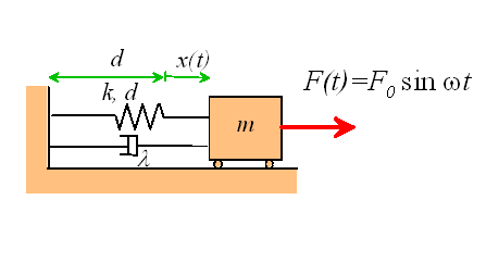
We will consider three types of forcing applied to the spring-mass system, as shown below:
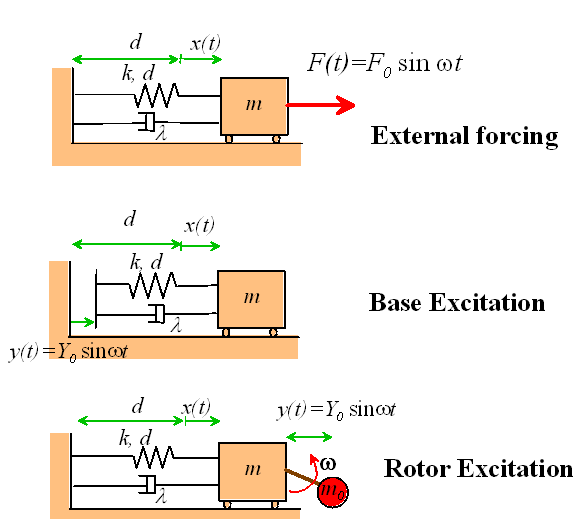
External Forcing models the behavior of a system which has a time varying force acting on it. An example might be an offshore structure subjected to wave loading.
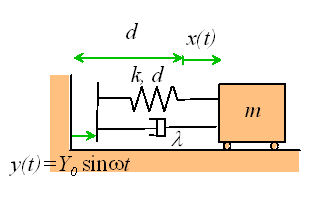
Base Excitation models the behavior of a vibration isolation system. The base of the spring is given a prescribed motion, causing the mass to vibrate. This system can be used to model a vehicle suspension system, or the earthquake response of a structure.
Rotor Excitation models the effect of a rotating machine mounted on a flexible
floor. The crank with small mass ![]() rotates at constant angular velocity, causing the mass m to
vibrate.
rotates at constant angular velocity, causing the mass m to
vibrate.
Notice that in each case, we will restrict our analysis to harmonic excitation. For example, the external force applied to the first system is given by
![]()
The force varies harmonically, with amplitude ![]() and frequency
and frequency ![]() . Similarly, the base motion for the second
system is
. Similarly, the base motion for the second
system is
![]()
and the distance between the small mass ![]() and the large mass m for the third system has the same form.
and the large mass m for the third system has the same form.
We assume that at time t=0, the initial position and velocity of each system is
![]()
In each case, we wish to calculate the displacement of the mass x from its static equilibrium configuration, as a function of time t. It is of particular interest to determine the influence of forcing amplitude and frequency on the motion of the mass.
We follow the same approach to analyze each system: we set up, and solve the equation of motion.
6.9.1 Equations of Motion for Forced Spring Mass Systems
Equation of Motion for External Forcing
We have no problem setting up and solving equations of motion by now. First draw a free body diagram for the system (neglecting gravity and reactions for simplicity)
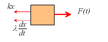
Newton II states that
![]()
Rearrange and susbstitute for F(t)
![]()
Check out our list of solutions to standard ODEs. We find that if we set
![]() ,
,
our equation can be reduced to the form
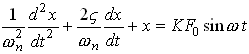
which is on the list.
The (horrible) solution to this equation is given in the list of solutions. We will discuss the solution later, after we have analyzed the other two systems.
Equation of Motion for Base Excitation
Exactly the same approach works for this system. The free body diagram is shown below, again with gravity and reactions neglected
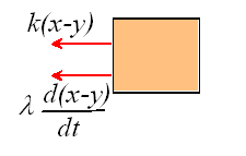
The force in the spring is now k(x-y) because the length of the spring is d+x-y. Similarly, the rate of change of length of the dashpot is d(x-y)/dt.
Newton’s second law then tells us that
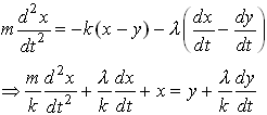
Make the following substitutions
![]()
and the equation reduces to the standard form
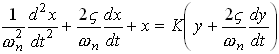
Given the initial conditions
![]()
and the base motion
![]()
we can look up the solution in our handy list of solutions to ODEs.
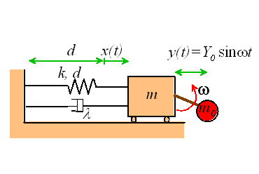
Equation of motion for Rotor Excitation
Finally, we will derive the equation of motion for the third case. Free body diagrams are shown below for both the rotor and the mass
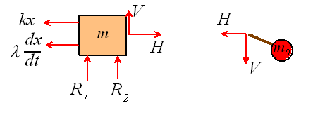
Note that the horizontal acceleration of the mass ![]() is
is
![]()
Hence, applying Newton’s second law in the horizontal direction for both masses:
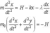
Add these two equations to eliminate H and rearrange
![]()
To arrange this into standard form, make the following substitutions
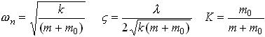
whereupon the equation of motion reduces to

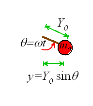
Finally, look at the picture below to convince yourself that if the crank rotates with
angular velocity ![]() , then
, then
![]()
where ![]() is the length of the crank.
is the length of the crank.
The solution can once again be found in the list of solutions to ODEs.
6.9.2 Definition of Transient and Steady State Response.
If you have looked at the list of solutions to the equations of motion we derived in the preceding section, you will have discovered that they look horrible. Unless you have a great deal of experience with visualizing equations, it is extremely difficult to work out what the equations are telling us.
This applet should help. The applet
simply calculates the solution to the equations of motion using the formulae given in the
list of solutions, and plots graphs showing features of the motion. You can use the
sliders to set various parameters in the system, including the type of forcing, its
amplitude and frequency; spring constant, damping coefficient and mass; as well as the
position and velocity of the mass at time t=0. Note that you can control the
properties of the spring-mass system in two ways: you can either set values for k, m
and ![]() using the sliders, or you
can set
using the sliders, or you
can set ![]() , K and
, K and ![]() instead.
instead.
We will use the applet to demonstrate a number of important features of forced vibrations, including the following:
The steady state response of a forced, damped, spring mass system is independent of the initial conditions.
To convince yourself of this, run the applet (click on `start’ and let the system run for a while). Now, press `stop’; change the initial position of the mass, and press `start’ again.
You will see that, after a while, the solution with the new initial conditions is exactly the same as it was before. Change the type of forcing, and repeat this test. You can change the initial velocity too, if you wish.
We call the behavior of the system as time gets very large the `steady state’ response; and as you see, it is independent of the initial position and velocity of the mass.
The behavior of the system while it is approaching the steady state is called the `transient’ response. The transient response depends on everything…
Now, reduce the damping coefficient and repeat the test. You will find that the system takes longer to reach steady state. Thus, the length of time to reach steady state depends on the properties of the system (and also the initial conditions).
The observation that the system always settles to a steady state has two important consequences. Firstly, we rarely know the initial conditions for a real engineering system (who knows what the position and velocity of a bridge is at time t=0?) . Now we know this doesn’t matter – the response is not sensitive to the initial conditions. Secondly, if we aren’t interested in the transient response, it turns out we can greatly simplify the horrible solutions to our equations of motion.
When analyzing forced vibrations, we (almost) always neglect the transient response of the system, and calculate only the steady state behavior.
If you look at the solutions to the equations of motion we calculated in the preceding sections, you will see that each solution has the form
![]()
The term ![]() accounts for the transient response, and is always zero for large time.
The second term gives the steady state response of the system.
accounts for the transient response, and is always zero for large time.
The second term gives the steady state response of the system.
Following standard convention, we will list only the steady state solutions below. You should bear in mind, however, that the steady state is only part of the solution, and is only valid if the time is large enough that the transient term can be neglected.
6.9.3 Summary of Steady-State Response of Forced Spring Mass Systems.
This section should be all you need to solve problems involving forced vibrations. The same information is also summarized on a handout (pdf format), which may be referred to in examinations.
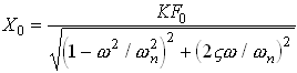
Solution for External Forcing
Equation of Motion
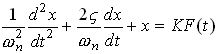
with
![]()
Steady State Solution:
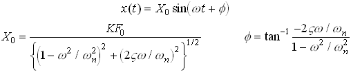
The expressions for ![]() and
and ![]() are graphed below, as a function
of
are graphed below, as a function
of ![]()
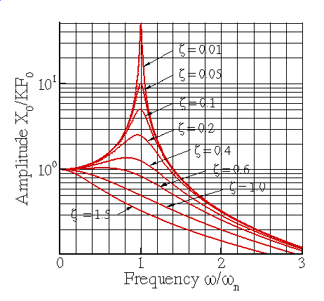
Steady state vibration amplitude of a forced spring—mass system.

Steady state phase of a forced spring—mass system
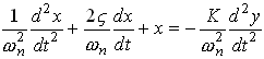
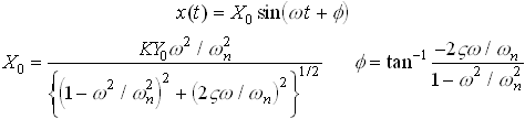
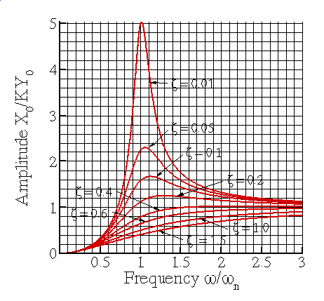
Solution for Base Excitation
Equation of Motion
with
![]()
Steady State solution
The expressions for ![]() and
and ![]() are graphed below, as a function
of
are graphed below, as a function
of ![]()
Steady state vibration amplitude for a base excited spring—mass system
Steady state phase for a base excited spring—mass system
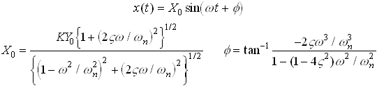
Solution for Rotor Excitation
Equation of Motion
with
Steady state solution
The expressions for ![]() and
and ![]() are graphed below, as a function
of
are graphed below, as a function
of ![]()
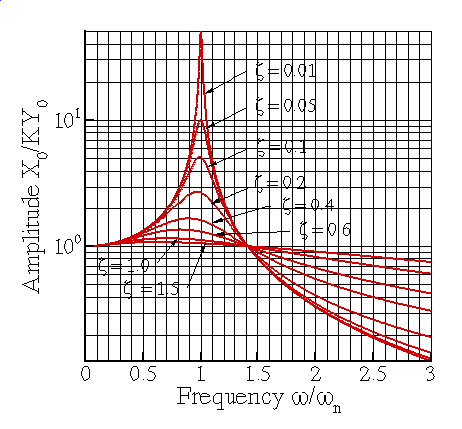
Steady state vibration amplitude for a rotor excited spring—mass system
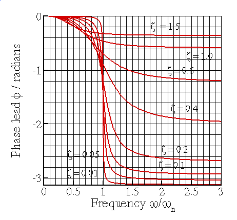
Steady state phase lead for a rotor excited spring—mass system
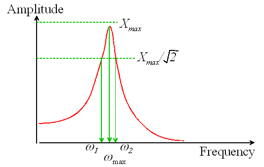
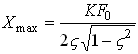
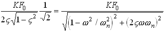
6.9.4 Features of the Steady State Response of Spring Mass Systems to Forced Vibrations.
Now, we will discuss the implications of the results in the preceding section.
![]() The
steady state response is always harmonic, and has the same frequency as that of the
forcing.
The
steady state response is always harmonic, and has the same frequency as that of the
forcing.