
3.2 Calculating forces required to cause prescribed motion of a particle
We use the following general procedure to solve problems like this
(1) Decide how to idealize the system (what are the particles?)
(2) Draw a free body diagram showing the forces acting on each particle
(3) Consider the kinematics
of the problem. The goal is to calculate the acceleration of each particle in
the system you may be able to start by writing down the
position vector and differentiating it, or you may be able to relate the
accelerations of two particles (eg if two particles move together, their
accelerations must be equal).
(4) Write down F=ma for each particle.
(5)
If you are solving a problem involving a massless frames (see, e.g. Example 3,
involving a bicycle with negligible mass) you also need to write down about the particle.
(5) Solve the resulting equations for any unknown components of force or acceleration (this is just like a statics problem, except the right hand side is not zero).
It is best to show how this is done by means of examples.
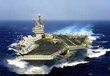 Example 1: Estimate the minimum thrust
that must be produced by the engines of an aircraft in order to take off from
the deck of an aircraft carrier (the figure is from www.lakehurst.navy.mil/NLWeb/media-library.asp)
Example 1: Estimate the minimum thrust
that must be produced by the engines of an aircraft in order to take off from
the deck of an aircraft carrier (the figure is from www.lakehurst.navy.mil/NLWeb/media-library.asp)
We
will estimate the acceleration required to reach takeoff speed, assuming the
aircraft accelerates from zero speed to takeoff speed along the deck of the
carrier, and then use
Data/ Assumptions:
1. The flight deck of a Nimitz class aircraft carrier is about 300m long (http://www.naval-technology.com/projects/nimitz/) but only a fraction of this is used for takeoff (the angled runway is used for landing). We will take the length of the runway to be d=200m
2. We will assume that the acceleration during takeoff roll is constant.
3. We will assume that the aircraft carrier is not moving
(this is wrong actually the aircraft carrier always moves at
high speed during takeoff. We neglect
motion to make the calculation simpler)
4. The FA18 Super Hornet is a typical aircraft used on a
carrier it has max catapult weight of m=15000kg http://www.boeing.com/defense-space/military/fa18ef/docs/EF_overview.pdf
5. The manufacturers are somewhat reticent about
performance specifications for the Hornet but 150 knots (77 m/s) is a reasonable guess for a
minimum controllable airspeed for this aircraft.
Calculations:
1. Idealization: We will idealize the aircraft as a particle. We can do this because the aircraft is not rotating during takeoff.
2.
 FBD: The figure
shows a free body diagram.
FBD: The figure
shows a free body diagram. represents the (unknown) force exerted on the
aircraft due to its engines.
3. Kinematics: We must calculate the acceleration required to reach takeoff speed. We are given (i) the distance to takeoff d, (ii) the takeoff speed and (iii) the aircraft is at rest at the start
of the takeoff roll. We can therefore write down the position vector r and velocity v of the aircraft at takeoff, and use the straight line motion
formulas for r and v to calculate the time t to reach takeoff speed and the
acceleration a. Taking the origin at the initial position of
the aircraft, we have that, at the instant of takeoff
This gives two scalar equations which can be solved for a and t
4. EOM: The vector equation of motion for this problem is
5. Solution: The i component of the equation of motion gives an equation for the unknown force in terms of known quantities
Substituting numbers gives the magnitude of the force as F=222 kN. This is very close, but slightly greater than, the 200kN (44000lb) thrust quoted on the spec sheet for the Hornet. Using a catapult to accelerate the aircraft, speeding up the aircraft carrier, and increasing thrust using an afterburner buys a margin of safety.
 Example 2: Mechanics
of Magic! You have no doubt seen the
simple `tablecloth trick’ in which a tablecloth is whipped out from underneath
a fully set table (if not, you can watch it at http://wm.kusa.gannett.edgestreams.net/news/1132187192333-11-16-05-spangler-2p.wmv)
Example 2: Mechanics
of Magic! You have no doubt seen the
simple `tablecloth trick’ in which a tablecloth is whipped out from underneath
a fully set table (if not, you can watch it at http://wm.kusa.gannett.edgestreams.net/news/1132187192333-11-16-05-spangler-2p.wmv)
In this problem we shall estimate the critical acceleration that must be imposed on the tablecloth to pull it from underneath the objects placed upon it.
We wish to determine conditions for the tablecloth to slip out from under the glass. We can do this by calculating the reaction forces acting between the glass and the tablecloth, and see whether or not slip will occur. It is best to calculate the forces required to make the glass move with the tablecloth (i.e. to prevent slip), and see if these forces are big enough to cause slip.
1. Idealization: We will assume that the glass behaves like a particle (again, we can do this because the glass does not rotate)
2.  FBD. The
figure shows a free body diagram for the glass.
The forces include (i) the weight; and (ii) the normal and tangential
components of reaction at the contact between the tablecloth and the glass. The normal and tangential forces must act
somewhere inside the contact area, but their position is unknown. For a more detailed discussion of contact
forces see Sects 2.4 and 2.5.
FBD. The
figure shows a free body diagram for the glass.
The forces include (i) the weight; and (ii) the normal and tangential
components of reaction at the contact between the tablecloth and the glass. The normal and tangential forces must act
somewhere inside the contact area, but their position is unknown. For a more detailed discussion of contact
forces see Sects 2.4 and 2.5.
3.
Kinematics We are assuming that the glass has the same
acceleration as the tablecloth. The table cloth is moving in the i direction, and has magnitude a. The acceleration vector is therefore .
4.
EOM.
5. Solution: The i and j components of the vector equation must each be satisfied (just as when you solve a statics problem), so that
Finally, we must use the friction law to decide whether or not the tablecloth will slip from under the glass. Recall that, for no slip, the friction force must satisfy
where
is the friction coefficient. Substituting for T and N from (5) shows
that for no slip
To
do the trick, therefore, the acceleration must exceed . For a friction coefficient of order 0.1, this
gives an acceleration of order
. There is a special trick to pulling the
tablecloth with a large acceleration
but that’s a secret.
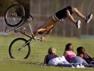 Example 3:
Bicycle Safety. If a bike rider brakes too hard on the front wheel, his
or her bike will tip over (the figure is from http://www.thosefunnypictures.com/picture/7658/bike-flip.html). In this example we investigate the conditions
that will lead the bike to capsize, and identify design variables that can
influence these conditions.
Example 3:
Bicycle Safety. If a bike rider brakes too hard on the front wheel, his
or her bike will tip over (the figure is from http://www.thosefunnypictures.com/picture/7658/bike-flip.html). In this example we investigate the conditions
that will lead the bike to capsize, and identify design variables that can
influence these conditions.
If
the bike tips over, the rear wheel leaves the ground. If this happens, the reaction force acting on
the wheel must be zero so we can detect the point where the bike is
just on the verge of tipping over by calculating the reaction forces, and
finding the conditions where the reaction force on the rear wheel is zero.
1.  Idealization:
a. We will idealize the rider as a particle (apologies to
bike racers but that’s how we think of you…). The particle
is located at the center of mass of the rider.
The figure shows the most important design parameters- these are the
height of the rider’s COM, the wheelbase L
and the distance of the COM from the rear wheel.
b. We assume that the bike is a massless frame. The wheels are also assumed to have no
mass. This means that the forces acting
on the wheels must satisfy and
- and can be analyzed using methods of
statics. If you’ve forgotten how to
think about statics of wheels, you should re-read the notes on this topic
in particular, make sure you understand the
nature of the forces acting on a freely rotating wheel (Section 2.4.6 of the
reference notes).
c.  We assume that the rider brakes so hard that the front
wheel is prevented from rotating. It
must therefore skid over the ground.
Friction will resist this sliding. We denote the friction coefficient at
the contact point B by
We assume that the rider brakes so hard that the front
wheel is prevented from rotating. It
must therefore skid over the ground.
Friction will resist this sliding. We denote the friction coefficient at
the contact point B by .
d. The rear wheel is assumed to rotate freely.
e. We neglect air resistance.
2. FBD. The figure shows a free body diagram for the rider and for the bike together. Note that
a. A normal and tangential force acts at the contact
point on the front wheel (in general, both normal and tangential forces always
act at contact points, unless the contact happens to be frictionless). Because the contact is slipping it is
essential to draw the friction force in the correct direction the force must resist the motion of the bike;
b. Only a normal force acts at the contact point on the rear wheel because it is freely rotating, and behaves like a 2-force member.
3. Kinematics The
bike is moving in the i direction.
As a vector, its acceleration is therefore ,
where a is unknown.
4. EOM: Because
this problem includes a massless frame, we must use two equations of motion ( and
). It is essential to take moments about the
particle (i.e. the rider’s COM).
gives
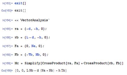
It’s very simple to do the moment calculation by hand, but for those of you who find such calculations unbearable here’s a Mathematica script to do it. The script simply writes out the position vectors of points A and B relative to the center of mass as 3D vectors, writes down the reactions at A and B as 3D vectors, and calculates the resultant moment (we don’t bother including the weight, because it acts at the origin and so exerts zero moment)
The two nonzero components
of and the one nonzero component of
give us three scalar equations
We
have four unknowns the reaction components
and the acceleration a so we need another equation.
The missing equation is the friction
law
5. Solution: Here’s the solution
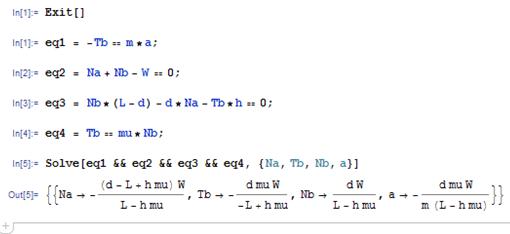
We are interested in finding what makes the reaction force at A go to zero (that’s when the bike is about to tip). So
 This tells us that the bike will tip if the friction
coefficient exceeds a critical magnitude, which depends on the geometry of the
bike. The simplest way to design a
tip-resistant bike is to make the height of the center of mass h small, and the distance (L-d) between the front wheel and the COM
as large as possible.
This tells us that the bike will tip if the friction
coefficient exceeds a critical magnitude, which depends on the geometry of the
bike. The simplest way to design a
tip-resistant bike is to make the height of the center of mass h small, and the distance (L-d) between the front wheel and the COM
as large as possible.
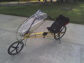
A
`recumbent’ bike is one way to achieve this the figure (from http://en.wikipedia.org/wiki/Recumbent_bicycle)
shows an example. The recumbent design offers many other significant advantages
over the classic bicycle besides tipping resistance.
 Example 4: A
stupid problem that you might find in the FE professional engineering exam. The
purpose of this problem is to show what you need to do to solve problems
involving more than one particle.
Example 4: A
stupid problem that you might find in the FE professional engineering exam. The
purpose of this problem is to show what you need to do to solve problems
involving more than one particle.
Two
weights of mass and
are connected by a cable passing over two
freely rotating pulleys as shown. They
are released, and the system begins to move.
Find an expression for the tension in the cable connecting the two
weights.
1.  Idealization
The masses will be idealized as particles; the
cable is inextensible and the mass of the pulleys is neglected. This means the internal forces in the cable,
and the forces acting between cables/pulleys must satisfy
and
,
and we can treat them as though they were in static equilibrium.
2.
FBD we have to draw a separate FBD for each
particle. Since the pulleys and cable
are massless, the tension T in the
cable is constant.
3. Kinematics We know that both masses must move in the j direction. We also know that the masses always move at the same speed but in opposite directions. Therefore, their accelerations must be equal and opposite. We can express this mathematically as
4. EOM: We must write down two equations of motion, as there are two masses
We
now have three equations for three unknowns (the unknowns are and T).
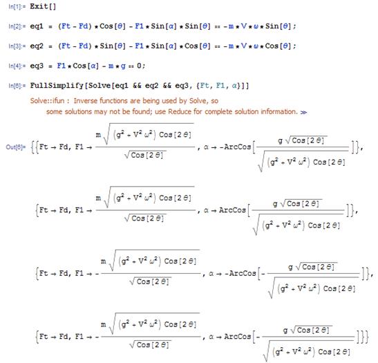
5. Solution: As paid up members of ALE (the Academy of Lazy Engineers) we use Mathematica to solve the equations
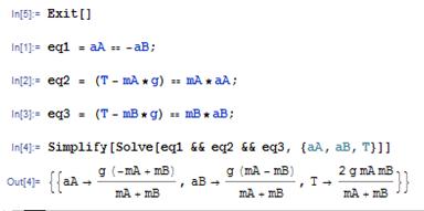
So the tension in the cable is
We pass!
 Example 5:
Another stupid FE exam problem: The figure
shows a small block on a rotating bar.
The contact between the block and the bar has friction coefficient
Example 5:
Another stupid FE exam problem: The figure
shows a small block on a rotating bar.
The contact between the block and the bar has friction coefficient . The bar rotates at constant angular speed
. Find the critical angular velocity that will
just make the block start to slip when
. Which way does the block slide?
The general approach to
this problem is the same as for the Magic trick example we will calculate the reaction force exerted
by the bar on the block, and see when the forces are large enough to cause slip
at the contact. We analyze the motion
assuming the slip does not occur, and
then find out the conditions where this can no longer be the case.
1.
 Idealization
 We will idealize the block as a particle. This is dangerous, because the block is
clearly rotating. We hope that because
it rotates at constant rate, the rotation will not have a significant effect
but we can only check this once we know how to
deal with rotational motion.
2. FBD: The figure shows a free body diagram for the block. The block is subjected to a vertical gravitational force, and reaction forces at the contact with the bar. Since we have assumed that the contact is not slipping, we can choose the direction of the tangential component of the reaction force arbitrarily. The resultant force on the block is
3. Kinematics We can use the circular motion formula to write down the acceleration of tbe block (see section 3.1.3)
4. EOM: The equation of motion is
5.
Solution: The i and j components of the equation of motion
can be solved for N and T Mathematica makes this painless
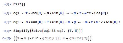
To find the point where the block just starts to slip, we use the friction law. Recall that, at the point of slip
For
the block to slip with
so
the critical angular velocity is . Since the tangential traction T is negative, and the friction force
must oppose sliding, the block must
slide outwards, i.e. r is increasing
during slip.
 Alternative
method of solution using normal-tangential coordinates
Alternative
method of solution using normal-tangential coordinates
We will solve this problem again, but this time we’ll use the short-cuts described in Section 3.1.4 to write down the acceleration vector, and we’ll write down the vectors in Newton’s laws of motion in terms of the unit vectors n and t normal and tangent to the object’s path.
(i)
Acceleration
vector If the block does not
slip, it moves with speed around a circular arc with radius r.
Its acceleration vector has magnitude
and direction parallel to the unit vector n.
 (ii) The force vector can be resolved into components
parallel to n and t.
Simple trig on the free body diagram shows that
(ii) The force vector can be resolved into components
parallel to n and t.
Simple trig on the free body diagram shows that
(iii) Newton’s laws then give
The components of this vector equation parallel to t and n yield two equations, with solution
This is the same solution as before. The short-cut makes the calculation slightly more straightforward.
 Example 6: Window
blinds. Have you ever wondered how window shades
work? You give the shade a little
downward jerk, let it go, and it winds itself up. If you pull the shade down slowly, it stays
down.
Example 6: Window
blinds. Have you ever wondered how window shades
work? You give the shade a little
downward jerk, let it go, and it winds itself up. If you pull the shade down slowly, it stays
down.
The
figure shows the mechanism (which probably only costs a few cents to
manufacture) that achieves this remarkable feat of engineering. It’s called an `inertial latch’ the same principle is used in the inertia
reels on the seatbelts in your car.
 The picture shows an enlarged end view of the window
shade. The hub, shown in brown, is fixed
to the bracket supporting the shade and cannot rotate. The drum, shown in peach, rotates as the
shade is pulled up or down. The drum is
attached to a torsional spring, which tends to cause the drum to rotate
counterclockwise, so winding up the shade.
The rotation is prevented by the small dogs, shown in red, which engage
with the teeth on the hub. You can pull
the shade downwards freely, since the dogs allow the drum to rotate
counterclockwise.
The picture shows an enlarged end view of the window
shade. The hub, shown in brown, is fixed
to the bracket supporting the shade and cannot rotate. The drum, shown in peach, rotates as the
shade is pulled up or down. The drum is
attached to a torsional spring, which tends to cause the drum to rotate
counterclockwise, so winding up the shade.
The rotation is prevented by the small dogs, shown in red, which engage
with the teeth on the hub. You can pull
the shade downwards freely, since the dogs allow the drum to rotate
counterclockwise.
To raise the shade, you need to give the end of the shade a jerk downwards, and then release it. When the drum rotates sufficiently quickly (we will calculate how quickly shortly) the dogs open up, as shown on the right. They remain open until the drum slows down, at which point the topmost dog drops and engages with the teeth on the hub, thereby locking up the shade once more.
We will estimate the critical rotation rate required to free the rotating drum.
1.
 Idealization
 We will idealize the topmost dog as a particle
on the end of a massless, inextensible rod, as shown in the figure.
a.
We will assume that the drum rotates at
constant angular rate . Our goal is to calculate the critical speed
where the dog is just on the point of dropping down to engage with the hub.
b.
When the drum spins
fast, the particle is contacts the outer rim of the drum a normal force acts at the contact. When the dog is on the point of dropping this
contact force goes to zero. So our goal
is to calculate the contact force, and then to find the critical rotation rate
where the force will drop to zero.
c. We neglect friction.
2. FBD. The figure shows a free body diagram for the particle. The particle is subjected to: (i) a reaction force N where it contacts the rim; (ii) a tension T in the link, and (iii) gravity. The resultant force is
3. Kinematics We can use the circular motion formula to write down the acceleration of the particle(see section 3.1.3)
4. EOM: The equation of motion is
5.
Solution: The i and j components of the equation of motion
can be solved for N and T Mathematica makes this painless
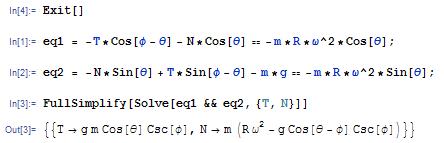
(the combine(%,trig) here just simplifies the trig formulas in the answer). The normal reaction force is therefore
We
are looking for the point where this can first become zero or negative. Note that
at the point where
=0. The
smallest value of N therefore occurs
at this point, and has magnitude
The critical speed where N=0 follows as
Changing the angle and the radius R gives a convenient way to control the critical speed in designing
an inertial latch.
Alternative solution using polar coordinates
 We’ll
work through the same problem again, but this time handle the vectors using
polar coordinates.
We’ll
work through the same problem again, but this time handle the vectors using
polar coordinates.
1. FBD. The figure shows a free body diagram for the particle. The particle is subjected to: (i) a reaction force N where it contacts the rim; (ii) a tension T in the link, and (iii) gravity. The resultant force is
2. Kinematics The acceleration vector is now
3. EOM: The equation of motion is
4. Solution: The
components of the equation of motion can be
solved for N and T
again, we can use MAPLE for this
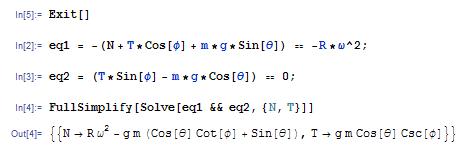
The normal reaction force is therefore
We
are looking for the point where this can first become zero or negative. Note that
at the point where
=0. The
smallest value of N therefore occurs
at this point, and has magnitude
The critical speed where N=0 follows as
Changing the angle and the radius R gives a convenient way to control the critical speed in designing
an inertial latch.
 Example 7:
Aircraft Dynamics Aircraft performing
certain instrument approach procedures (such as holding patterns or procedure
turns) are required to make all turns at a standard rate, so that a complete
360 degree turn takes 2 minutes. All
turns must be made at constant altitude and constant speed, V.
Example 7:
Aircraft Dynamics Aircraft performing
certain instrument approach procedures (such as holding patterns or procedure
turns) are required to make all turns at a standard rate, so that a complete
360 degree turn takes 2 minutes. All
turns must be made at constant altitude and constant speed, V.
People
who design instrument approach procedures need to know the radius of the
resulting turn, to make sure the aircraft won’t hit anything. Engineers designing the aircraft are
interested in the forces needed to complete the turn specifically, the load factor, which is the ratio of the lift force on the aircraft
to its weight.
In this problem we will calculate the radius of the turn R and the bank angle required, as well as the load factor caused by the maneuver, as a function of the aircraft speed V.
Before starting the calculation, it is helpful to understand what makes an aircraft travel in a circular path. Recall that
1. If an object travels at constant speed around a circle, its acceleration vector has constant magnitude, and has direction towards the center of the circle
2. A force must act on the aircraft to produce this
acceleration i.e. the resultant force on the aircraft must
act towards the center of the circle.
The necessary force comes from the
horizontal component of the lift force
the pilot banks the wings, so that the lift
acts at an angle to the vertical.
With this insight, we expect to be able to use the equations of motion to calculate the forces.
1.
Idealization The aircraft is idealized as a particle
it’s not obvious that this is accurate,
because the aircraft clearly rotates as it travels around the curve. However, the forces we wish to calculate turn
out to be fully determined by F=ma and are not influenced by the
rotational motion.
2.
FBD. The figure shows a free body diagram for the
aircraft. It is subjected to (i) a
gravitational force (mg); (ii) a
thrust from the engines ,
(iii) a drag force
,
acting perpendicular to the direction of motion, and (iv) a lift force
,
acting perpendicular to the plane of the wings.
The resultant force is
(you may find the components of the lift force
difficult to visualize to see where these come from, note that the
lift force can be projected onto components along OR and the k direction as
. Then note that
.)
3. Kinematics
a.
The aircraft moves at
constant speed around a circle, so the angle ,
where
is the (constant)
angular speed of the line OP. Since the aircraft completes a turn in two
minutes, we know that
rad/sec
b. The position vector of the plane is
We can differentiate this expression with respect to time to find the velocity
c.
The magnitude of
the velocity is ,
so if the aircraft flies at speed V,
the radius of the turn must be
d. Differentiating the velocity gives the acceleration
4. EOM: The equation of motion is
5.
Solution: The i j and k components of the equation of motion give three equations that
can be solved for ,
and
. We assume that the drag force is known, since
this is a function of the aircraft’s speed.
Mathematica does a lousy job here (that’s because it doesn’t make any assumptions about whether variables are positive, negative, real or imaginary so it finds a lot of solutions that are not relevant). Negative lift forces and bank angles are unphysical, and can be ignored. It’s actually easier to solve the equations by hand, which shows that
We can calculate values of ,
and the load factor
for a few aircraft
a.
Cessna 150 V=70knots
(36 m/s) :
R=690m,
b.
Boeing 747: V=200
knots (102 m/s) R=1950m,
c.
F111 V=300 knots (154 m/s) R=2950m,
 Alternative
solution using normal-tangential coordinates
Alternative
solution using normal-tangential coordinates
This problem can also be solved rather more quickly using normal and tangential basis vectors.
(i) Acceleration vector. The aircraft travels around a circular path at constant speed, so its acceleration is
where n is a unit vector pointing towards the center of the circle.
(ii) Force vector. The force vector can be written in terms of the unit vectors n,t,k as
(iii) Newton’s law
The
n, t and k components of
this equation give three equations that can be solved for ,
and
. As before, the solution is