Division of Engineering
Brown University
2.6 Curvilinear motion II: Analyzing motion in a moving basis
In Section 2.4, we solved some problems involving particles moving along arbitrary paths. In each case, we chose to describe vectors as components referred to a fixed {i,j,k} basis.

This is not always the most convenient way to solve a problem. For example, suppose you wanted to compute the forces acting on a car as it travels around a bend.
You would find it most convenient to refer force components to a basis that travels with the car – it is much more helpful to know the lateral, vertical and longitudinal forces acting on the vehicle than the forces acting in the Northerly, Easterly and vertical direction.
In this section, we will develop the tools to describe motion using a moving basis.
Two general approaches will be discussed.
Using Normal and Tangential coordinates for planar motion

Consider a particle, which moves along a curved path. Assume that the path of the particle is known. For example, the particle could represent our car, travelling along a road. We know that the car must stay on the road, so we only need to specify how far down the road the car has traveled in order to determine its position.
The position of the particle, then, is specified by the arc length s traveled along the path, from some arbitrary (but fixed) origin.
We could, if we wished, specify the particle’s position, velocity and acceleration by stating the components of each vector in a fixed {i,j,k} basis, as shown in the picture.
We don’t usually do this, however. Instead, we use a basis that moves with the particle, as follows.
![]() One of the basis vectors,
One of the basis vectors, ![]() , is chosen to point in
the direction of increasing s (tangent to the path).
, is chosen to point in
the direction of increasing s (tangent to the path).
![]() A second basis vector,
A second basis vector, ![]() , is taken to be normal to the
direction of travel. THIS VECTOR MUST ALWAYS POINT TOWARDS THE CENTER
OF CURVATURE OF THE PATH (if the path is a straight line, you can choose
any direction for
, is taken to be normal to the
direction of travel. THIS VECTOR MUST ALWAYS POINT TOWARDS THE CENTER
OF CURVATURE OF THE PATH (if the path is a straight line, you can choose
any direction for ![]() , as long as it is normal to
, as long as it is normal to ![]() ).
).
![]() A third basis vector is defined as
A third basis vector is defined as ![]() . The three vectors
form a right handed triad, and all three vectors must have unit length.
. The three vectors
form a right handed triad, and all three vectors must have unit length.
All vectors: forces, position, velocity and acceleration, are then expressed as components in this basis. The components are called `normal and tangential coordinates.’
This means we write

Some observations:
![]() In many of the problems we solve in this course, we will be concerned
with planar motion, so that
In many of the problems we solve in this course, we will be concerned
with planar motion, so that ![]()
![]() To determine the components of F, we use exactly the same
procedure as we used when solving problems in a fixed basis. You simply
need to resolve F into components along
To determine the components of F, we use exactly the same
procedure as we used when solving problems in a fixed basis. You simply
need to resolve F into components along ![]() and
and ![]() instead
of components along i and j.
instead
of components along i and j.
![]() It is usually painful to work out the components of r.
Fortunately we almost never have to do this.
It is usually painful to work out the components of r.
Fortunately we almost never have to do this.
![]() Recall that the velocity vector always points tangent to the
path traveled by the particle. This means that
Recall that the velocity vector always points tangent to the
path traveled by the particle. This means that ![]() , i.e. the velocity
may be expressed as
, i.e. the velocity
may be expressed as
The magnitude of the velocity, ![]() , is the distance traveled by the
particle per unit time, i.e.
, is the distance traveled by the
particle per unit time, i.e.
This leaves the acceleration to be determined. In particular, we need
to relate ![]() and
and ![]() to the velocity
to the velocity ![]() and the path
of the particle. This is the main new idea in this section.
and the path
of the particle. This is the main new idea in this section.
Velocity-Acceleration relations for normal-tangential coordinates
To keep things simple, we will start by assuming that our particle moves along a circular path. We will later generalize this to arbitrary planar paths. Introduced basis vectors
![]() as shown. Note that we have chosen
as shown. Note that we have chosen ![]() to point tangent
to the path in the direction of travel, and that
to point tangent
to the path in the direction of travel, and that ![]() points towards
the center of curvature of the path (the center of the circle, in our case)
points towards
the center of curvature of the path (the center of the circle, in our case)

We have seen that the velocity of the particle may be expressed as
We could compute the acceleration by differentiating with respect to time
The problem is, our basis vectors vary with time, as the basis rotates. We need to know how to differentiate the vectors with respect to time.
We will introduce an extremely important result here. It should really be in a section by itself, but it’s more helpful to put it here where we need it.
Time derivative of a rotating unit vector
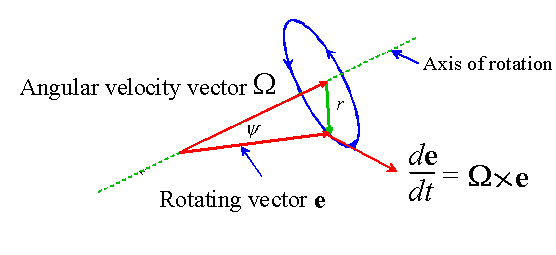
Suppose that a unit vector e rotates with angular velocity vector
![]() . Its time derivative is then given by
. Its time derivative is then given by
The symbol ![]() denotes a cross product (or vector product).
denotes a cross product (or vector product).

The figure above is helpful in proving this result. Suppose that the
unit vector e spins about the axis shown in the picture with angular
velocity ![]() . The tip of the vector describes a circular path as
shown in blue. The radius of the circle is given by
. The tip of the vector describes a circular path as
shown in blue. The radius of the circle is given by
![]() , where
, where ![]() is the angle between e and
is the angle between e and ![]() .
.
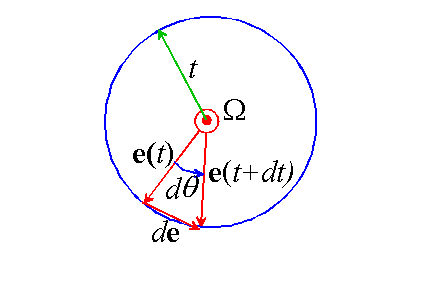
Now, imagine looking down the axis of rotation, so that the vector ![]() points
towards you. Suppose we freeze the motion at some time t. You would
see the vector e pointing up out of the page towards you, at an
angle
points
towards you. Suppose we freeze the motion at some time t. You would
see the vector e pointing up out of the page towards you, at an
angle ![]() to the perpendicular. Now, let the vector rotate for
a short time dt. The vector rotates through a small angle
to the perpendicular. Now, let the vector rotate for
a short time dt. The vector rotates through a small angle ![]() and
so points in a slightly different direction, as shown in the picture below.
and
so points in a slightly different direction, as shown in the picture below.

Note that the angle follows as
from the definition of angular velocity. Observe that the vector e changes by a small amount
during the time interval dt.
We can write down an expression for de by noting that
- The direction of de is perpendicular to both e
and

- The length of de is

Now, consider the vector ![]() . Recall that, by definition, the
length of this vector is
. Recall that, by definition, the
length of this vector is
where we have noted that ![]() because e is a unit vector.
Recall also that the direction of
because e is a unit vector.
Recall also that the direction of ![]() is perpendicular to both
e and
is perpendicular to both
e and ![]() .
.
Therefore

as required.

Time derivatives of basis vectors
Let’s apply this result to compute the time derivatives of each
of the ![]() basis vectors in the picture above.
basis vectors in the picture above.
We have already found the angular velocity of the radial line OA: recall that
The angular velocity of each basis vector must be the same as that of the line OA, since the angle between OA and each vector remains constant.
Therefore

Similarly

Finally,
(If you are worried about how to go about computing cross products of the basis vectors, you can use any of the techniques that you are familiar with for a fixed {i,j,k} basis. For
example, you can use the determinant approach

Another approach can be found in the handout reviewing vectors).
The Velocity-Acceleration Relation
Finally, we are able to derive the result we need. Recall that
Hence, using the result above

All three expressions are equivalent; you can use whichever is more convenient. It is important that you understand how these results were derived, however, because we will encounter problems that are best solved by going back to the derivation rather than applying these formulae.
The two terms in the expression for a have some physical significance. Recall that a particle accelerates for two reasons: (i) its speed changes or (ii) its direction of travel changes. The first term in a is due to the rate of change of speed of the particle. The second term is due to the change in direction of travel.
Position-velocity-acceleration relations for arbitrary paths
We now extend our results to situations where the particle is moving along a general curved path, not just a circular path as in the preceding section.
It turns out to be quite easy to do this. At any point on the path, we can approximate the path of the particle as a circle. This is illustrated below.

The picture shows the radius of curvature ![]() and
and ![]() at two points
along the path.
at two points
along the path.
In most problems we solve in this course, the radius of curvature of
the path of the particle will be given to you. On rare occasions, you might
be told the shape of the path as a function, for example you might be told
that ![]() . In this case it is useful to recall an elementary result
from analytic geometry
. In this case it is useful to recall an elementary result
from analytic geometry
