 EN3:
Introduction to Engineering and Statics
EN3:
Introduction to Engineering and Statics
Advanced Section
Homework 7
Due 12:00 noon Thursday, November 11, 2004.
67 Points total
Division of Engineering
Brown University
1. A
Fink roof truss is shown below. It is subjected to a snow load, distributed as
shown 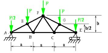
a. Determine the reactions at points A and D as a function of P, a and b. 3 points
b. Use the method of sections to determine the force in member BC of the truss. Be sure to draw a free body diagram showing all forces acting on the relevant section of the truss. 2 points
2. An aluminum bicycle spoke is 30 cm long and has a 2 mm diameter. ;
a. Calculate the stiffness of the bar when loaded in the elastic regime, in N/m. 2 points
b. Calculate the maximum force that the spoke can withstand without permanent deformation, in Newtons. 2 points
c. Calculate the buckling load for the bar, in Newtons 2 points
3. The figure shows a simple model for a front bicycle wheel with 3 spokes. The rim is assumed to be rigid, and the spokes are pinned at each end. The central hub is subjected to a force W as shown. All spokes are aluminum with radius 1mm, length L0=0.3m and stiffness k. In this problem you will examine the forces in the spokes as a function of the orientation q of the wheel. The second picture is simply rotated to align the axes with the horizontal and vertical directions.

a. Due to the load on the hub, the hub displaces as shown below. Write down expressions for the deformed lengths of members DA, DB and DC, in terms of . If you have trouble seeing the geometry right away, remember that you can find the lengths of the members using vectors. 3 points

b. Find a formula for the potential energy of deformation for the structure, in terms of k, . You need not substitute for in terms of ux and uy from part b.
2 points
c. Find a formula for the potential energy of the force Fw= in terms of the hub displacement components , force magnitude W, and angle q. 1 point
d. Find a formula for the total potential energy of the structure in terms of W, q, L0, k, ux, uy and . 1 point
e. Find formulas for the internal forces in members DA, DB and DC in terms of k, . 2 points
f. Program an EXCEL spreadsheet that will calculate the values of by minimizing the potential energy of the structure. Add a section to the spreadsheet that will calculate the forces in the spokes. Use your spreadsheet to calculate the internal forces in the members for L0=30 cm and k as calculated above. Let , and show results for q=0 and p/6. 8 points
g. Which orientation produces higher stresses? Are any of the spoke forces above the yield load? Are the forces in the compressive members above the buckling load? In problem 5 below, you will see that the spokes are given an initial pre-tension when placed in the wheel in order to avoid buckling in the spokes under loading. 3 points
4. Read through the tutorial for the 2D structural analysis spreadsheet, available here (no solution is required for this problem) More details can be found in section 11 of the enotes. 0 points
5. Consider the bike wheel with 20 spokes radially arranged on a rigid rim. The spokes have length L0=.3 meters and radius 1mm. The hub joint is number 1, and has coordinates (0,0). The ith joint has coordinates (xi,yi)=(L0 sin(2p(i-1)/20), L0 cos(2p(i-1)/20)) i=2…21. These joints are pinned to the rigid rim, and therefore are constrained to have zero deflection.
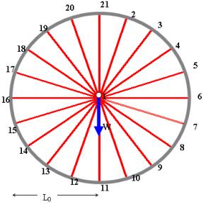
Set up the Excel 2-D program to calculate the force in each spoke under a vertical load W=500 Newtons to the hub. Use the spoke stiffness calculated in problem 2 above.
a. Report the deflection of the hub. 5 points
b. Show the forces in the spokes. 5 points
c. Is any spoke at or above its yield load? 2 points.
d. Is any spoke at or above its critical buckling load? 2 points
e. Spokes on bicycles are actually prestressed. They have length L0<0.3m when they are in their relaxed state. Thus, when they are strung together in the bike, they have a tensile force of T0=k(0.3m-L0). The forces in a prestressed spoke under load W can be estimated as the initial tension T0 plus the forces solved for in part b above. If the total force in each prestressed spoke under the load W=500N is not to exceed ½ the critical buckling load, calculate the value of the pretension T0 and initial length Lo required.
Note that you only have to consider the spoke with the largest compressive force -Tmax, and find T0 such that T0-Tmax>Pcr/2. 3 points
6. Recall the spacecraft lander leg from the previous homework. A mock up is to be made from ½” PVC tubular members; the dimensions and properties of these members can be found in the design project specifications. The objective of this problem is to use the 3D structural analysis spreadsheet to calculate the internal forces in the members. You will want to use this spreadsheet for your design project.
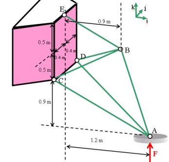
a. Calculate the stiffness of all the members. Express your answer in N/m. You may find it helpful to use EXCEL to do the calculations. If you like, you could do the calculation by inserting a worksheet into the 3D structural analysis worksheet, in which case you can use the structural analysis spreadsheet to automatically calculate member lengths (the distances between all the joints are in the `Calculations’ sheet. 5 points
b. Calculate the maximum load that each member can withstand without fracture or rupture, expressing your answer in Newtons. 1 point
c. Calculate the buckling load for each member in the structure, expressing your answer in Newtons. 5 points
d. For the mock up, F=100Newtons. Use the excel spreadsheet to find the internal loads. Will the structure support the load? 8 points