
Hint: define for yourself what the input condition SR=11 causes in the circuit on the left.
1. Combinational circuits and asynchronous circuits both change their outputs after fresh input arrives. So what's the difference between the two kinds of circuits?
2. What's the difference between these two circuits?

Hint: define for yourself what the input condition SR=11 causes in the circuit on the left.
3. Same output, different input sequences. need to say how many input changes, etc.
Here is an asynchronous circuit with 2? outputs. Assume the current output is PQ=10.
Figure out two different input sequences which can lead to the output PQ=10. Don't let
the sequences be longer than 4? input changes.
4. Timing problems in combinational circuits.
(a) Consider the design for an EXOR gate, from �1,

Assume each gate, including the inverter, has a 10 nanosecond propagation delay.
Suppose we arrange for A and B to change simultaneously from 00 to 11. Does the output
stay at 0, as we would hope, or is there a glitch? What about a change from BA=11 to 00?
Are there any glitches when only one input at a time changes?
(b) A three input K-map is realized with the NAND circuit shown to the right--

Assume each NAND gate and the inverter have a propagation delay of 10 nanoseconds. When the inputs change simultaneously from CBA=011 to CBA=101, we expect the output to stay at 1; however, due to delay through the inverter, gate G2 will stay at 1 for 10 nanoseconds longer than G1 will switch from 0 to 1, resulting in a 10 nanosecond glitch of 0 at OUT. Draw a timing diagram to show the glitch, and propose a solution which will remove the glitch [hint: consider the law of consensus].
If you have one available, try working out the solutions on a logic simulator, where you can look at a timing diagram [Dig-Sim 2.2]
5. PACMAN� has 4 buttons: UP, DOWN, LEFT, RIGHT. A player cannot actually start to
press two buttons simultaneously.
(a) What input restriction is imposed on the button inputs?
In fact, PACMAN can go in only one of U, D, L, R direction at any one time, so at most one
input to the movement control circuit can be active at a time. [If all inputs are inactive,
PACMAN doesn't move.]

(b) Now what restriction is placed on the circuit input? Can the INPUT mode circuit be
combinational only? What circuitry can accomplish this input specification? If, after no
buttons are pressed, an input button is pressed, then that button's action is in effect until
it is released, no matter what other buttons are pressed.
(c) Now suppose that the most recently pressed button is the one which governs
PACMAN movement (e.g. If UP is in action then LEFT button is pressed, PACMAN will start
moving left). Design a circuit to meet this requirement.
6. Consider the slotted joystick below, for use in the game TETRIS.

Only when the stick is moved into one of the four slots is an input action asserted. Assume
the actions ROTATE, DROP and MOVE await a signal from the joystick before being
executed.
(a) Is a sequential circuit required to implement the joystick output?
(b) What about the command MOVE LEFT? Is a sequential circuit required to implement
it?
(c) What (mechanically) can be added to or changed on the joystick to allow simultaneous
ROTATE and shift?
7. Is it possible to turn a set of pulse mode inputs into fundamental mode inputs? What must the fundamental mode system know about the starting and stopping of various inputs?
8. Spatial processing. Imagine three photodetectors, spaced 1 cm apart, inspecting
limited regions of the X axis, turned on by the presence of a spot, which hops either left
or right 1 cm at at time. At the end of each hop the spot lands in front of one of the
photodetectors, causing it to produce a HI output. The photodetectors are labelled as
shown below.
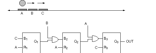
(a) Will the circuit above respond to left movement, right movement, both or neither?
(b) If all Q's are 0 and the spot is at B, then how far must the spot move before OUT is 1?
(c) Once OUT becomes 1, what can cause it to reset to 0?
9. A circuit has two inputs, P and C, and one output OUT. If P goes HI, then OUT goes
HI until C goes HI, at which time OUT goes to LO. If both P and C are HI at the same time,
then OUT goes to (or stays) LO. See timing diagram below.

Design an asynchronous circuit which meets these specifications. Does the circuit remind you of anything you've seen before?
10. In playing Jeopardy three contestants A, B, & C can press 3 buttons at almost the same
time. A circuit is needed which keeps the first signal high while disabling the other two.
The following is proposed:
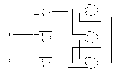
Assuming propagation delay for FF, inverter and AND gates are all 10 ns.
(a) If A goes high at t = 0 ns;
B goes high at t = 100 ns;
C goes high at t = 110 ns
Will the circuit work as desired?
(b) What if B goes high at t = 10 ns while C goes high at t = 110 ns ?
(c) What is the minimum time difference between the first and the second signals for the
circuit above to function properly ?
(d) If all the gates you have have 20 ns propagation delay, is it possible to design a circuit
to do the job correctly for timing in (b) ?
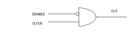
11. We want to design a gating circuit with two inputs: DISABLE and CLOCK. If DISABLE
is HIGH, changes in the CLOCK input is neglected. If DISABLE is LOW, output will be just
the CLOCK input. Will the following circuit work ? You may want to study the timing diagram
first.
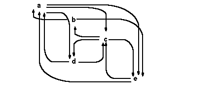
12. What is/are invalid with the flow diagram below?
13. Refer to the flow diagram below:
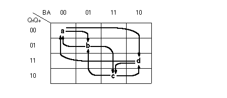
(a) How many cycles can you identify? What state transitions do they represent?
A realization of the above flow diagram is given below:
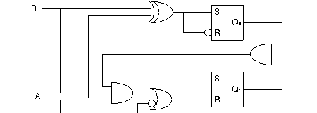
(b) Find all cycles that give rise to critical race condition.
(c) How would you reassign the FF outputs to the states a - d to eliminate the race cycles?
(d) Design a circuit for your flow diagram in (c).
14. The finite state machine represented below cannot be implemented if each row of the
flow table has only 1 stable state. Why? Consider fundamental mode restriction.

15. A 1-bit latch can be built as follows:
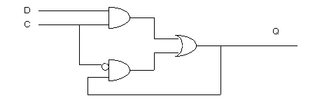
(a) Draw the corresponding flow table.
(b) Do you think it works ? (i.e. under what circumstances, if any, will an output glitch
occur?)
16. A system has two external inputs, K and L, and one output, OUT. Its primitive flow table
is shown below. Each row is a "different" primitive state.
(a) Which pairs of states in the system's primitive flow table can be merged? Begin by
labelling the destinations of the transient states for each input change. The first row is done
for you.
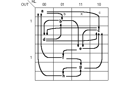
You will need to fill in half a matrix where rows and columns are both labelled by states.
Each white box should have a Y or N, indicating whether the two states can be merged or
not.
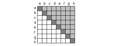
(b) What if we require that merged states have the same value of OUT?
(c) Merge pairs of states, then go through a second round of merging. How few states can
you end up with?
17. (a) What do the K-maps for S and R look like for the key-in-lock design of example
1, shown below?

(b) How many of the squares in the QRS K-map represent stable states?
18. The state diagram below shows two paths to "unlock" a system at state 11. Design a
2-flip flop sequential circuit to realize this system.

19. What is the briefest input sequence which will send the system below from
Q1Q0 = 00 to 11? Does the circuit have a reset to return to Q1Q0 = 00 ?

20. Analyze the following circuit, and figure out an input sequence which will make OUT
go high, if the system starts in state QYX=011.

If you need to know, when the flip flop inputs are SR=11, then Q = 0, and propagation delay through all gates is 20 nsec.
21. What are the stable states of the following asynchronous circuit?

Inputs are A and B. If the circuit is re-drawn with one flip flop above the other, then the projections from the Q's will be seen as feedback. Cut the feedback paths and analyze the circuit with 4 inputs--A, B, current Q1 and current Q0. A stable state is one in which
next Q = current Q.
Let a state be described by a combination of Q1 Q0 B A.
22. The informal design of the window discriminator, example 2, is shown below.

(a) What do the K-maps for each S and R look like?
(b) Where is there feedback in this circuit?
(c) Is this a Mealy or Moore circuit?
(d*) From the K-maps, can you infer a state diagram?
23. The systematic method for a window discriminator design (page XXX) was modified to eliminate a critical race. In the text the new logic expression for S1 was left as an exercise. Referring back to the window discriminator example worked in the text, figure out what is the proper expression for S1 to eliminate the race.
24. In S4 a 1-shot is designed with and SR flip flop and feedback from an RC charging
circuit. Show, by drawing out timing diagrams, the consequences of a SET pulse occurring
during the RESET pulse.
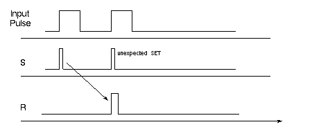
Analyze 2 cases, one where SR=11 causes the flip flop to go LO (NOR) and the other where
SR=11 causes the flip flop to go HI (NAND).
25. Use 1-shots to create the output shown below from one input pulse:

26. Another look at input restriction in the electronic lock. Say that pressing any two
buttons simultaneously will re-lock the system. Design a combinational circuit which will
respond with HI when any 2 out of 4 inputs are active simultaneously.

Show where in a circuit the output of the 2/4 circuit can go to re-lock the "lock-and-key"
solution to the electronic lock example (page XXX).
Properly used, the 2/4 circuit enforces a condition that mimicks the pulse mode in the
electronic lock.
27. Design a synchronous electronic lock, with the specifications of Example 2.
Assume a pulse generator with a frequency of 1000 Hz supplies the clock input. How fast
can the lock be unlocked?
28. Could we use a deMUX to enforce the pulse mode restriction on the electronic lock?
What should select be? What happens as you change from one input to another? Is a
"zero" choice needed on the deMUX output?

[ANS: can't make transition from 00 to 11, or from 10 to 01. Need
to code the ABCDs to permit "fundamental mode" action on select!
Let B, D, C, A = 00, 01, 11, 10 select codes.]
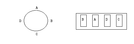
29. Consider two kinds of locks, one in which you rotate back and forth between numbers,
and the other in which you set 4 or 5 numbers on tumblers then pull the lock open. Which
of these locks is like an asynchronous circuit, and which is like a combinational circuit?
30. Clock gating. A clock is gated by another signal, on its way to OUT. If the gating signal
is HI, then clocks pulses are allowed through. We want to make sure every clock pulse has
the same active-high width, so if the gate goes LO!HI during the time clock, the system
waits for the next active-high clock pulse phase before allowing a clock pulse through to
OUT. If the gate goes HI!LO during the active-high phase of clock, then the current clock
pulse is allowed to finish before other clock pulses are blocked from OUT. A timing diagram
is shown below.

DESIGN AN ASYNCHRONOUS CIRCUIT WHICH WILL MEET REQUIREMENTS for the two inputs CLK and GATE, and one output, OUT.
Given the a propagation delay of 10 nsec per gate or flip flop, what is the fastest clock frequency your system can tolerate, and still meet the restriction of the fundamental mode?
31. Asynchronous halt for for a clock. A clock signal must be interrupted by a "halt" input
which will stop the clock at whichever value the clock was at when the halt went HI. Timing
possibilities are shown below:
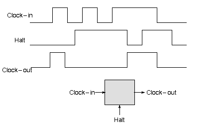
Design an asynchronous circuit which will meet the specification for the clock halt
operation. Anther term for the circuit you will design is "transparent latch". When halt = LO,
clock-in is passed "transparently" to clock-out; when halt = HI, the last value of
clock-out is "latched" (or held) until halt returns to LO.
32. Complete the "wasteful design" for example 1, started in the text. Can any of the six SR flip flops be replaced directly with combinational gates?
33. In �11 you saw an example of an oscillating flip flop. Under what circumstances do the
following designs oscillate?
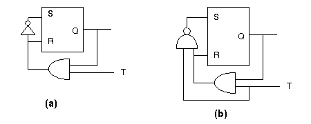
When input T goes from 1 to 0, what is the output Q for the two circuits?
34. In the circuit below, X1 and X2 are inputs while Y1 and Y2 are outputs.
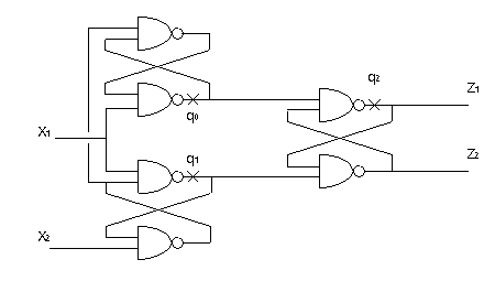
(a) To analyze the above circuit, we make cuts at the 3 "x" to obtain the following
sub-circuits:
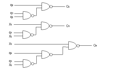
draw the Karnaugh map for the outputs Q0Q1Q2.
(b) How many states in your Karnaugh map are stable?
(c) Draw the flow diagram for the original cicruit.
(d) What do you think the circuit does?
35. Refer to the previous problem. Analyze the cicuit if all NAND gates are changed to NOR gates.
36. Refer to the following diagram:
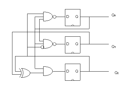
(a) What sequence do you think the above circuit will step through if all 3 FFs are run by
the same clock and Q2Q1Q0 = 000 initially?
(b) Why is it impossible to have the output equal 6 after the second clock tick ?
(c) Given that we are in state 011, if you can treat the 3 clock inputs as separate inputs,
what is the shortest input sequence that can change the output to 111 ?
37. Many telephone answering machines have a "1/4" option by which the machine will
wait four rings before answering if there are no messages on its tape, but will pick up after
one ring if there are messages. This feature tells someone calling in remote if there are any
messages. Assume there are two external inputs-"ring" and "tone"-and one internal
input-end-of-announcement (E-O-A). The external output is "voice." Internally,
outputs turn on the announcement or message tapes.
Let's say there is a mechanism for setting a "flag" if a message has been recorded but not
listened to.
In what follows, assume "analog switches" are the gates to be controlled by the logic you
will design.
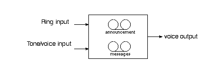
(a) Design an asynchronous circuit for the machine which can pick up after the proper
number of rings for the 1/4 option. By "pick up" we mean ignore further rings until "hang
up," and be ready to send voice output. Assume each "ring" is a pulse of 500 msec
duration, with 1 second between rings; and that only full-length rings occur.
(b) Design a message record feature. After pick up, the announcement plays to output
until E-O-A signal, at which time a message on the voice input is recorded as a message.
After message is recorded the machine "hangs up". To hang up means to listen again for
rings.
(c) Assume now that the answering machine can respond to an incoming tone during the
announcement phase, and if the proper incoming tone is heard, the machine will stop the
announcement and play back any messages on its message tape. Design an
asynchronous circuit circuit for remote access.
A real answering machine is more complicated and must have a minimum amount of
analog circuitry for detecting rings and tones, recording voice input on tape, etc. Modern
telecommunications equipment (fax, answering machine, cellular phone, etc) often
contains both digital and analog circuitry. (cite 10/91 NYT article...)
Digital vs Analog: "complicated functions in easy-to-build chips, vs simple functions in
hard-to-build chips"
7/91 CHECK THE NEXT PROBLEM. IT'S FROM THE OLD DAYS (1988)
38. When a switch is in the D1 position we want repeated presses of the the input button to
sequence through
0 00
1 01
3 11
0 00
repeat;
but if the switch is in the D2 position, we want the opposite sequence,
3 11
1 01
0 00
3 11
repeat.
The switch will never be in the D1 and D2 positions at the same time. Whichever of the two
inputs is not selected will be 0. Furthermore, selection of D1 or D2 will be made only during
time when the input button is LO (circuit is stable).
Design an asynchronous solution, using toggle (T) flip flops; two will be needed.

Let the toggle flip flops be positive edge-triggered on their "clock" input.
Since these are toggle flip flops, we only care about times when an input D1 or D2 arrives HI
and is able to cause a state change. As a consequence, there are only two cases to worry
about: D2, D1 = 01 & D2, D1 = 10. You need to fill in the following state-change tables, for
inputs T0 and T1: Q1 and Q0 are the more and less significant bits of the answer, respectively.

The combination for D1 active (01) is the left column of each pair.
		blackjack
mention oscillators, 1-shots, delays?
39. Vending machine. A coin slot in a vending machine accepts 5�, 10�, and 25� coins. Only one coin at a time can be dropped into the coin slot. As it passes the "coin detector", the coin causes one of three outputs on the detector to give an active-high pulse. Design a circuit which will give a HI output after exactly 30� worth of coins have been dropped into the slot. If more than 30� is dropped into the slot, a RESTART output goes HI and stay HI until the next coin is dropped in. After RESTART goes HI, the user can try again to drop 30� into the vending machine. Don't get nickel'd and dime'd to death.
40. What sequence(s), if any, of inputs (DCBA) will cause output to go HI in the following?
Assume all flip flop outputs are zero before starting, and that only one input at a time can
change. If SR=11, then Q=1. Consider only sequences of 5 input changes or less
(a) If inputs obey pulse mode restriction?
(b) If inputs are allowed to obey fundamental mode restriction?
(c) Once the output is HI, what input(s) will reset both flip flops?

What if the circuit is changed to below, and SR=11 results in Q=0? How would the above questions be answered?

NEED PROBLEM ON 1-SHOT
*41.If we tried to make an oscillator with the following circuit,
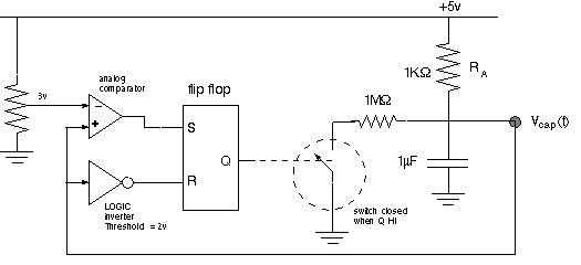
will it work? If not, can you change something to make it oscillate?
42. Delay. (a) Show how a D-flip flop can be used as a delay element.

Waveform A must be delayed until the time shown on the figure.
(b) Reset. Now consider use of a clocked SR flip flop as a timing element. Let S receive
and input to be delayed. What input should go to R?
43. How is the flushing of a toilet like a one shot?
44. Design an oscillator using rising edge triggered 1-shots.
45. (a) Using 1-shots, design a 3-shot (a circuit which, when presented with a rising
edge, responds with exactly 3 pulses). To be more specific, say that the width of the three
pulses is D and the two intervals between the three pulses are also D.

(b) Can you make a three shot with one 1-shot and two delay elements?
46. Another Electronic lock. A lock has two input buttons, E and F. Each time E or F is
pressed, an E-pulse or F-pulse is generated internally. The lock opens if the sequence
E E F F E F
is pressed. If more than 6 presses are attempted before OUT goes HI, the system resets
itself so that the entire correct sequence needs to be re-entered. Pressing EEEFFEF won't
work.
Design a circuit which will un-lock only for the correct input sequence.
Use T-flip flops in your design.
47. We used 5 states and three flip flops for the T-flip flop version of the electronic lock, example 3. Can you make a successful design with only 2 T flip flops? Draw out a state diagram, if you think it's possible.
48. The German psychologist Carl Jung developed the concept of synchronicity, the
simultaneous occurrence of a mental and a physical event, supposedly heralding a
significance between the two events. Design a synchronicity detector. Imagine there are
two sub-circuits, one of which responds with a pulse when a mental event occurs, and
the other which responds when a physical event occurs. Design a circuit which responds
with a HI output if the mental and physical events occur within 400 msec of each other.
Libit: timing and consciousness
see Emperor's New Mind, by Roger Penrose, last chapter...
Problem on Synchronizers.