Background:
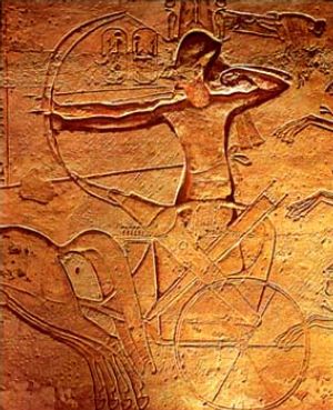
The chariot was introduced into Egypt during the Second Intermediate Period by the Hyksos. By the New Kingdom it had become an integral part of the Egyptian military. The basic construction of the chariot is outlined in pages 77 through 80 of Tutankhamun's Armies by Darnell and Manassa, however a much more thorough description of the construction of Ancient Egyptian chariots is given in Chariots and Related Equipment from the Tomb of Tut'Ankhamun. This book clearly describes the chariots found in King Tut's tomb and includes dimensions for all of the parts of the chariot. It is from these descriptions and the relief of Ramses II at the Battle of Kadesh found at Abu Simbel that I am basing the design and construction of my Ancient Egyptian chariot.
Design:
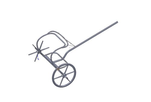
Below is a picture of the chariot that I intend to build as designed in SolidWorks. Overall the design is very similar to chariot A-1 as discussed in Chariots and Related Equipment, with many dimensions for the wheel, spokes and nave (the hub) being derived from chariots A-5 and A-6. The rear upper handle bar has a slight slant backwards similar to the chariot of Ramses II as depicted at the Battle of Kadesh.
All of the dimensions derived from chariots A-1, A-5 and A-6 only serve as guides, and the actual dimensions of the designed chariot are all rounded to the nearest 1/32" due to the limits of woodshop measureing tools and techniques. Some dimensions (such as the inner diameter of the wheel) are rounded to the nearest inch or standard board thickness, due to the foreseen inaccuracies of steam bending and to make cutting and machining easier.
Construction:
Steam Bending and Shaping:
The curves of the chariot are all attained by bending solid pieces of wood. The exact way that the Ancient Egyptians did this is unknown, however some suggest that it might have been accomplished by boiling the pieces of wood in water and then bending the wood around a form. I, however, will be using the more modern (though still very old) technique of steam bending. Steam bending involves placing the wood into a chamber full of steam to soften the wood up, then bending the wood around a desired form. The next few paragraphs are to describe the process of steam bending.
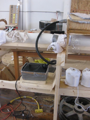
To steam bend a piece of wood, a steam chamber is first constructed. For this project, two steam chambers were constructed (pictured below). One is a very long PVC pipe with a wye in the center, a cap at one end and a screw cap at the other end. The second chamber is wider than the 3" PVC tube to accommodate the wide pieces of wood used for the spokes and is constructed from cheap plywood. The steam from a one gallon wallpaper steamer is fed into the PVC tube from the wye, and into the plywood steamer from a hole in the rear. The steam is released through small holes in either end of the PVC tube and from a slight opening in the front panel of the plywood to prevent excess pressure from building up and leading to an explosion. It is crucial for good bending that the temperature in these chambers reaches or exceeds 212 degrees Fahrenheit. To accomplish this, fiber glass insulation was wrapped around the PVC tube, and Reflix was placed on the inside wall of the wider chamber. Also, 700 grams of salt (an entire container of Morton Salt) was added to the wallpaper steamer to raise the boiling temperature of the water up to 222 degrees Fahrenheit, and a lining of Reflix was added. The wood is steamed for a fifteen minutes per quarter inch of thickness ( the smallest dimension on a piece of wood).
In order to accomplish a desired curve, the right wood had to be selected. Different woods have different minimum curvature radii that can be accomplished through steam bending. Chart 1 below, lists the best woods to be bent, the radii that can be accomplished with and without a backing strap. The Egyptian chariots were constructed with a combination of elm, ash and willow. Because elm is very scarce and expensive in North America (due to Dutch Elm disease) I decided not to use it on the chariot. I ended up choosing white oak because of its excellent bending abilities compared to all other woods and because I can get it for a great price :). Upon deciding on white oak, I had to choose from two different varieties, kiln-dried or green. Green white oak is white oak that has been freshly cut and has a moisture content of around 20 to 30 percent. It is by far the easier to bend of the two, however, it is harder to come by. Kiln-dried white oak is white oak that has been dried for a period of several months down to a moisture content of around 7 percent. It is much easier to come by, by it is more expensive, harder to bend and has to be soaked in water before bending. I located a sawmill, Brightman Lumber, which sells small quantities of green white oak at about 1/8 the price of the cheapest price of kiln-dried white oak that I could find.
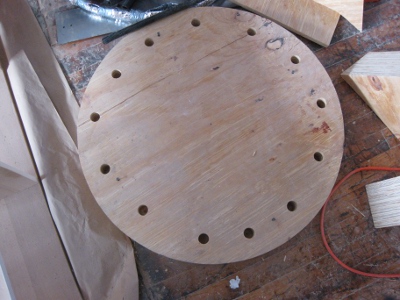
While I was deciding on which wood to use, I constructed the molds around which the wood to construct the spokes, the wheel and tire were to be constructed. They are all made of plywood and bandsawed to the desired shape. There are numerous holes to attach the clamps to hold the wood in place while it dries (which takes anywhere from 24 hours to a few months).
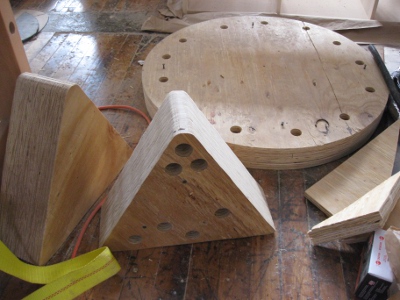
In order to accomplish these tight bends, a bendable jig was constructed which has handles at either end and a steel strap onto which the piece to bent is placed. The wood is placed on this jig so that the steel strap is on the outer side of the bend. When the wood and the jig are bent around the form, the handles and the steel strap prevent the outer edge from expanding and failing due to tension, and keep the inner edge under compression (wood is much stronger under compression than tension). For this project, the metal straps are laser cut from 16 gauge cold rolled steel to the width and length of the piece to be bended. Because the steel strap must remain in the mold with the wood while it dries, around 10 pieces of steel strap had to be cut for the wheels.
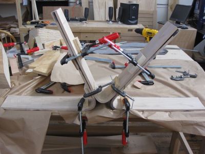
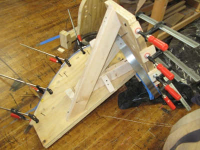
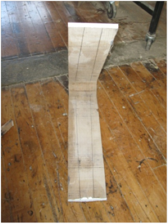
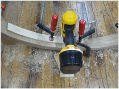
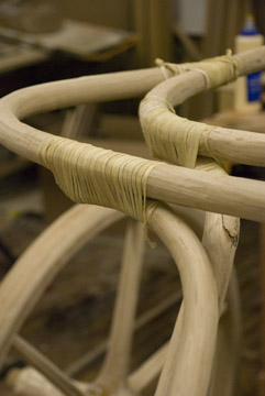
Pictures are given below of the first round of steam bending for the spokes. To bend the 1/2" stock of white oak, I needed three people including myself to help initially bend and clamp the piece. The first piece slightly fractured at the area of the bend, however after shaping and carving away that area so that the nave fit, the split disappeared. Because of the success, six other spokes were bent.
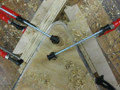
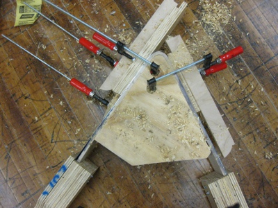
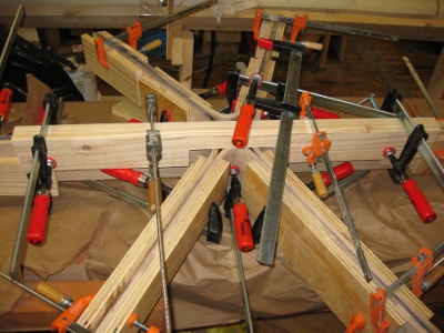
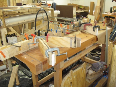
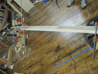
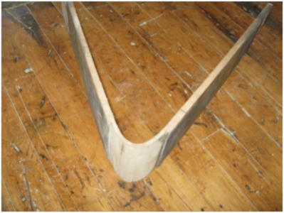
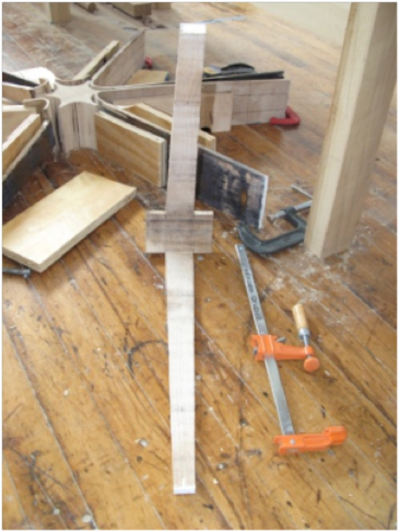
After the first three spokes were steamed and dried (a period of two days), they were removed from their molds and clamped together to the table, to ensure a 180 degree alignment. Checking (fracturing at the ends due to the rapid drying of end grain) occurred within a few days, but paint was applied to the ends of these and all other pieces to stop further occurences. While these threee were drying, the next three spokes were bent. After two days, they were clamped to the original three and a section of two by four was clamped across the center portion (again to ensure near symmetry). Pictures of these processes as well as the used rusted steel straps are below.
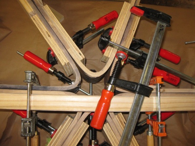
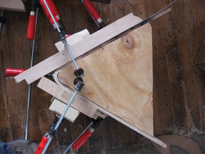
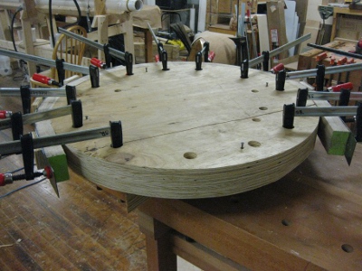
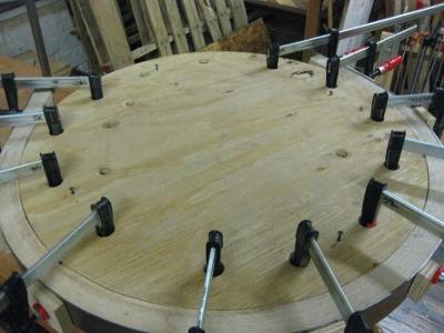
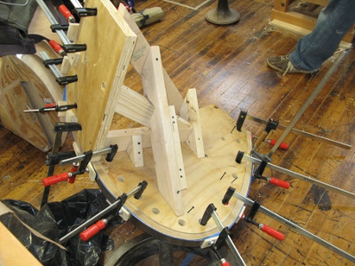
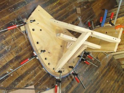
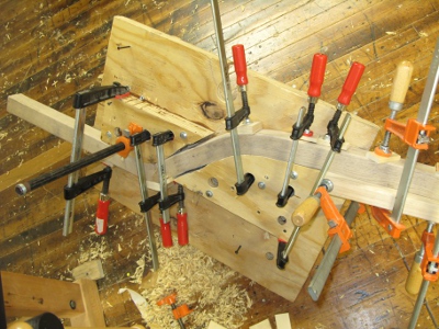
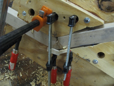
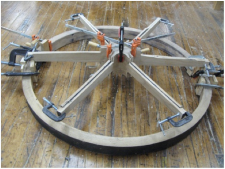
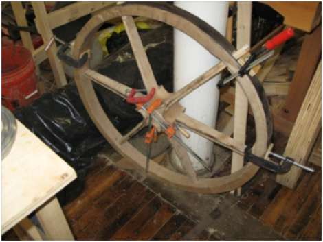
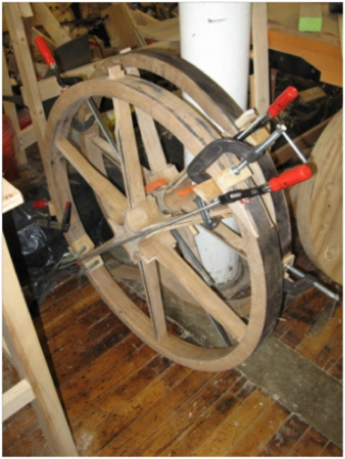
The next round of steam bending included the first half of the wheel. This required four people: two to brace the table, one to clamp the piece as it was bent around the form and another just to bend the stock. The first attempt failed, but revealed that in order to bend the piece, the mold had to be physically attached to the table. In order to accomplish this, dogs (ong metal rods) were run between holes in the table and the mold. The second attempt to bend the first half of the wheel succeeded, however, like the first spoke, slight fracturing occured at an improperly supported area. Again like the spoke, this did not effect the final piece, but to prevent this from happening again, all of the pieces to be bent are going to be chamfered (a suggestion of the steam bending literature). Below are several pictures of the bent wheel.
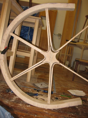
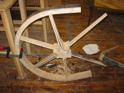
After the wheel was bent and while it was drying for four days, the spokes underwent the first round of shaping to fit them into the wheel and the ash nave (the hub) was shaped and placed in the center of the wheel. The wheel was mortised (holes were put in it to receive the spokes) and the ends of the spokes were fit into the wheel.
The ability to produce a wheel was proven, so the wood for the rest of the chariot was ordered. This order was deeply flawed. Knots (not ideal for bending) were scattered along the length of the boards and the grain direction (the alignment of the wood straws) was not consistent. However, pieces were scavenged off of these boards and another local provider of green white oak was found. To use the wood from these flawed boards, the second wheel was divided into thirds, so that longer, straighter pieces of white oak were not required.
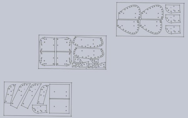
As all of this was going on, the next round of jigs was being designed and built. The CAD drawings are below, along with pictures of the jigs before being cut from their sheets of plywood. To save on time, all of these jigs were CNC'ed.
Meanwhile the design of the chariot was edited to minimize costs. The 1" diameter of the front support pieces was changed to 1 1/4" and the diameter of the axle extensions was increased to 1 3/4". These two edits ensured that only two round-over bits, 5/8" radius and 7/8" radius, were needed for the entire contruction of the chariot; saving about $200 on round-over bits. [To clarify, round-over bits create a round-over, or round, on an edge. So using a 5/8" radius round-over bit on all four edges of a 1 1/4" square stock of wood will create a dowel of diamter 1 1/4".] Overall, these changes do not effect the appearance of the chariot.
The next piece to be created was the axle. Kiln-dried, rather than green (freshly cut and still moist), wood was chosen because kiln-dried wood will not warp nearly as much as green wood over time. Several different kindswoods were considered: ash, poplar and white oak. Out of the three candidates, ash was the most ideal, and probably the wood used by the Egyptians to make the axle. However, it was mistakenly cut up to make other pieces of the chariot. Poplar was considered because it is by far the cheapest of the three woods, but does not have the strength of the other three. White oak was finally settled on due to its strength and availability to this chariot maker.
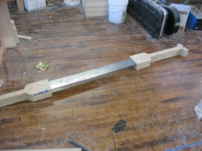
The first attempt to create the axle involved a cutting and millling a strip of wood to the desired 2" x 2" x 91.75" dimensions. The dato blade (a thick blade for the table saw) was used to create the thinner extensions at either end of the axle on which the wheels would rest. Next, a 7/8" inch radius round-over bit was used to make the extensions into dowels suitable for receiving the wheels. However, due to the size of the piece and the lack of sizable reference surfaces on the machines, the dowels at either end of the axle were not circular, or even close to circular.
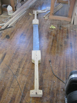
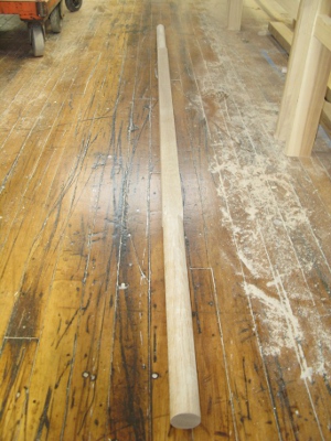
The second attempt involved milling a strip of white oak down to the dowel dimensions of 1.75" x 1.75" with the same length as the overall axle (91.75"). Next, the dowels at either end were rounded over using the 7/8" round-over bit. The result were much cleaner dowels. To increase the thickness in the center of the axle (to increase its overall bending strength) strips of 1/8" thickness veneer (thin pieces of wood) were cut from the first axle attempt and glued to the second attempt. The overall effect was to produce thicker and thinner segment of the axle while still keeping very accurate section of dowel on which the wheels can ride. To finish the axle, the center portion was rounded over using the 7/8" bit. Pictures of these two axles and practice pieces are below.
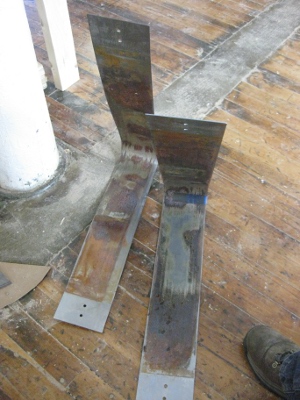
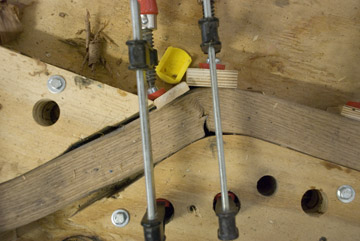
As the axle was being constructed, the first attempt to bend the central rod was occurring. This bend forms the center pole of the chariot, to which the chariot is lashed. It is by far the most difficult bend, as the bending radii of the 2" inch thick stock are 5" and 10". A double strap (two straps welded together by a c-channel) is required to support the back of each bend and prevent splitting. The bend failed because a weak double strap (a strap made from two straps welded together), a weak bending jig and a lack of a hole on the inner radius of the tighter bend (which would have reduced the stresses imposed on the entire set-up). From this failure, the maker learned that the reason for the notch on the rod was to reduced stress when bending and NOT solely to support the frame (as originally had been assumed).
After the axle was made, the maker examined all of the pieces previously bent and realized that they were checking due to fast and uneven drying. This problem was solved by applying ample amounts of a chemical called Pentacryl. This chemical allows the chariot maker to shorten the drying time of the wood down to less than one month, rather than waiting a year, like the Egyptians.
Meanwhile, the spokes for the other wheel were created similarly to the first batch of spokes. Next, the pieces for the center body of the chariot were bent and the other thirds and halves of the wheels were steamed. The side railing was the most difficult, requiring two straps welded perpendicular to eachother to reinforce it. The front railing was a straightforward bend, as well as the bottom and front support railings. Pictures of all of these bends are below as well as pictures of the bolts used to bend the wheels (notice that they are deformed, there's that much stress on the bolts!).
Finally came the last re-do of the central rod. The jig (mold around which the piece of wood is bent) was rebuilt much stronger. The piece of plywood were glued together and screws and bolts went through the piece. These all ensured that the mold was rock solid. A kerf cut ( a notch in the wood) was made on the inner part of the tighter radius bend. This relieved some of the stress induced by bending in two directions. The bend succeeded overall, with some minor breaking occurring around the tighter radius (caused by the strap slipping). Pictures of the final piece in the mold are below to enjoy!
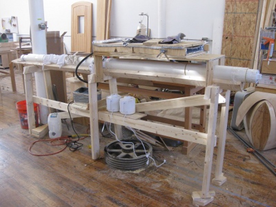
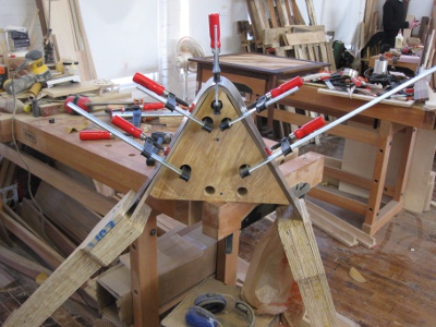
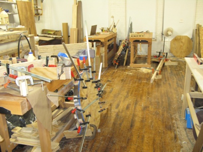
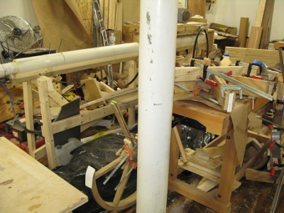
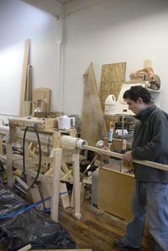
Below are some pictures of the shop that the chariot is being constructed in (with various jigs scattered around).
After all of the pieces were steam bent, the final wheel pieces were taken off of their respective jigs, aligned, carved and centered.
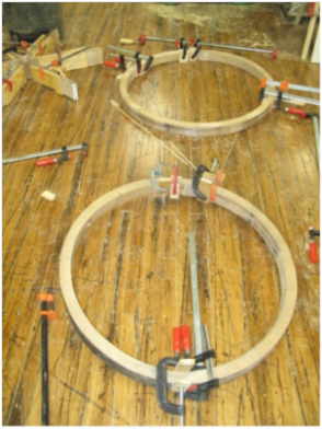
Clamps were used to hold the wheels together while the wheels and other freshly bent pieces of the chariot dried for about two weeks.
While the pieces were drying, the hub extensions were formed by wrapping thin pieces of paperbacked veneer around a paper-thickened axle. Wood glue was used to connect the layers.
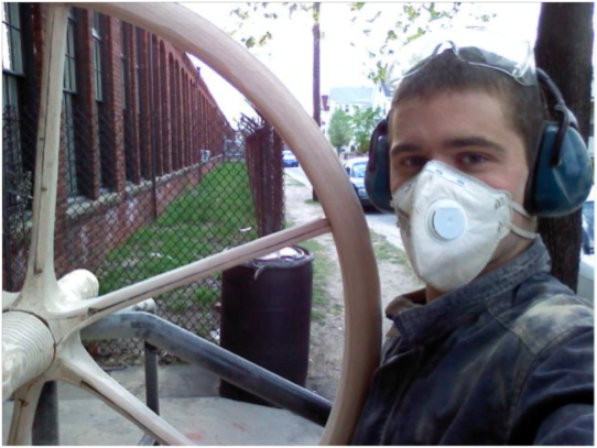
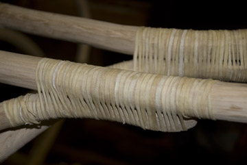
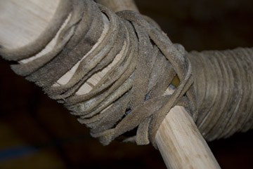
Finally, after the pieces had dried, they were shaped, cut to the appropriate lengths and joined together with dowels and rawhide (similar to how the Egyptians would have assembled their chariots). Not having the time to add an extra set of tires onto the outside of the inner tires, I cut a thin strip of white oak and glued it to the outside of the inner tires. This added extra strength to the wheels but was not visible once the strips of rawhide (which protect the wheel surface). The small gaps in the wheels were filled with epoxy with wood flour. Pictures of the shaping of the wheels outside of the studio (with a very non-Egyptian angle grinder) are below. The wheels went from looking like the rectangular wheels above to the smooth finished products below.
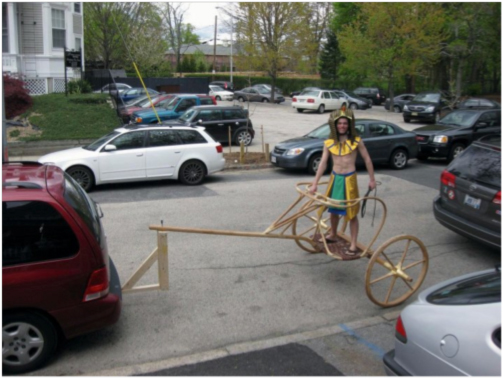
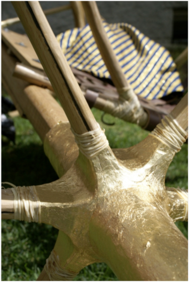
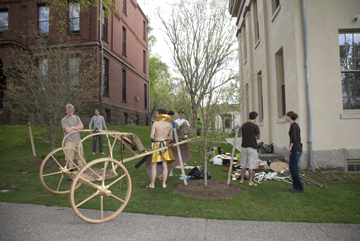
After the chariot had been assembled, the main body was determined to be too rocky. Two semi-circular supports were added to form an X support on the front portion of the chariot. The hub was gessoed and covered in faux-gold leaf. Wood finish was applied to all of the wood surfaces. Final pictures of the finished chariot are below. On a trial run, the chariot (hitched up to a mini-van) reached 30 mph.
Prof. B here...
I had a chance to talk to Sean extensively while he was building the chariot and after, and I learned a great deal from him. I'll put up a few photos from my two visits to the studio as well as a couple from the use of the chariot. It is a work of art as well as obviously a weapon. (Riding in it while nearly 9 months pregnant? possibly not my best idea ever, but I wasn't going to miss it. And Norah stayed in another couple of weeks and came out fine. Anyway, we only got to about 3 or 4 mph, not the 30 Sean took it to later.)
Here you see Sean putting a piece of wood into his custom-built steaming machine (basically a piece of pcv attached to a steam producing unit). Next to that is a bend that partly broke the wood despite a notch cut to relieve the pressure; this was the second attempt at bending the central post as the first try broke too thoroughly to be useable. The bending was the thing I noted most because in some ways it was puzzling to Sean. He was curious about how the Egyptians might have done it - his molds were wood but without the steel straps and clamps he would have had a much more difficult time doing it. He recently went to NY and saw one of Tutankhamun's chariots and observed to me that the wood had many more knots than he expected. He says this would have been fatal to bending, and wondered if in fact the trees had been trained to bend - a process of growing the right wood instead of bending it. This would obviously make the process of building a chariot a much, much longer one. If this is the case (and I haven't done enough research yet to know if it's an accepted idea, though I think Sean's experience itself is a valuable piece of evidence in favor) then we really aren't looking at equipping an army in response to a specific need, but more as a matter of course (and prestige). I got to see one steam bend being done and it was impressive - they took the wood out and had to work very quickly to wrap it to the frame and clamp it.
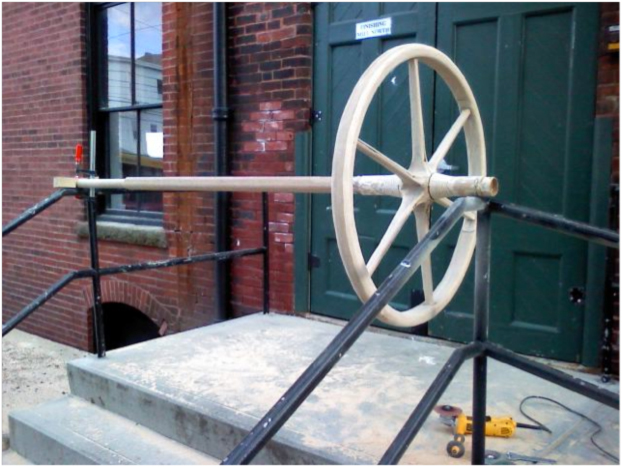
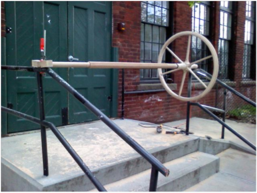
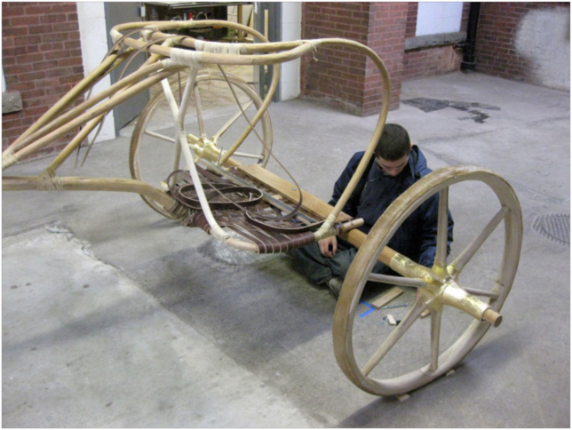
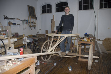
Here Sean is standing in the partly complete chariot - the wheels still haven't been smoothed, nor the platform woven. The attachment of the wheels to the carriage was one of the only non-authentic bits of the final chariot (as opposed to the production process), being done with steel bolts. This enabled Sean to take the wheels off the carriage (though not off the axel). The chariot was displayed for several days in Rhode Island Hall after the battle, and spent some time living in my office, too. We couldn't have gotten it in the door if we couldn't disassemble it - that wheel base is broad. Following are details of the attachments with hide.
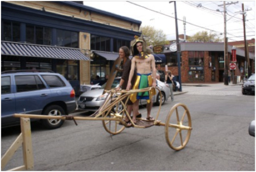
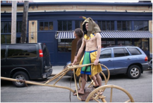
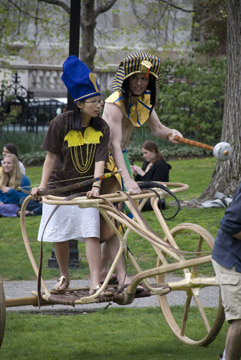
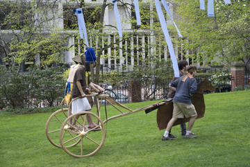
Riding the chariot to the scene of the battle. It actually would have been much easier if we had been standing up straighter and holding on to the reins instead of trying to hold onto the frame. My back and legs hurt by the time we got there, though of course my balance was off from the pregnancy.
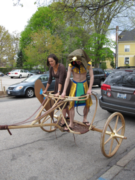
Before the battle. The mind boggles to think of two Ramesses in one chariot...
And finally, after loading the chariot into the van to take it north, Sean reassembled it and got it to an insane 30mph. See it (really, truly, see it) at the following: [link]
