where v is the the velocity of charge q, B is the magnetic field and E is the electric field.
Equations to set up an understanding of rotating machinery
¶ Lorentz equation and torque on armature loop
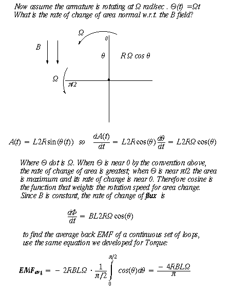
¶ Back EMF derived from Faraday's equation
¶ Invoking Lenz' Law for sign of back EMF
¶ Torque Speed curve from KVL
¶ Calculating power delivered to load
¶ Generator and Braking sections of curve
¶ Brushless (no commutator) DC motor design
Reading:
from Kenjo & Nagamori, Permanent Magnet and Brushless DC Motors,
Oxford University Press, 1985. pages 2-17 of chapter 1.
David McCauley, The (new) Way Things Work, Houghton-Mifflin (1998),
pp 280-81.
Consider the Lorentz force:
![]()
where v is the the velocity of charge q, B is the magnetic field
and E is the electric field.
Put the second term of the Lorentz equation in differential form:
![]()
Let a wire of length L carry a current I in a direction perpendicular to magnetic
field B:
By the right hand rule the direction of the force is into the page.
Now integrate the differential form:
If that wire is part of a rectangular loop with upper and lower sides L and height 2R ("radius") then following diagram, with the loop going into the page, and the current source in the form of a battery Vs and resistor Ra shown, we have the following forces:
therefore there is a torque on the loop, with 2*F*R the magnitude of the torque,
substituting our force formula,
![]()
How to get around the 3/8 turn limit? Commutator!
CW or CCW? As given to you in the example
above, with you facing the commutator, the rotation is counter-clockwise (CCW).
What change would be necessary for the rotation to turn CW? Reverse the sign
of the voltage source sending current through the coils!
Example: How a cone-type speaker works, with a permanent
magnet surrounding a coil. The coil has the sound wave AC current pass through
it. http://www.djsociety.org/Speaker_1.htm.
take the cross product of the wires coming out of the page and going into the
page, with the B field being reversed (top and bottom) to see the movement of
the cone the coil is attached to, going left and right above. The AC in the
coils creates audio-range sinusoids. Audio amplifiers increase the current through
the coils.

![]()
Note that KE, the EMF factor, is the same formula as KT, the torque factor.
What about the minus sign in the back EMF formula? We do know from Lenz' Law
that the correct sign of the back EMF must be as shown below. Therefore the
notation "KΩ" refers to the back EMF correctly labelled. We
will carry the constant through the succeeding calculation.
If torque is 0 then ΩMAX = V0 (the "maximum"
rotational speed) = Vs/K.
If rot. speed Ω=0 then T0 = KV/Rs
Notice what happens as the external voltage Vs drops: both max torque and max speed drop. The red line above moves closer to the origin.
Where Z (the number of turns) comes in:
And with Z turns the torque exerted by the motor is now T = Z*K*I(t).
Power delivered: Power is Torque X
speed. At zero speed or zero torque power is zero, and so too at Ω-MAX
. If you multiply the expression above for torque by Ω you will have a
second order expression for power as a function of rotation speed--an upward
pointing parabola. Where will Power be maximum?
A different answer would appears when considering rotational speed for maximum power in Hill's equation for muscle. See notes for Lab VT...
Braking
When the motor is made to turn against its natural direction, it acts as a brake.
The electric energy brakes the mechanical. Both mechanical and electrical energy
enter the motor and it is in danger of overheating.
How will electric braking work in an electric train going downhill? Reverse the
voltage to the motor!
Generator
When the motor is turned in the direction to produce a back EMF, it acts as
a generator (the tach in the Fan Lab). Consider the case where no battery voltage
is applied: an EMF will be seen; or if there is a chemical battery (like in
car engine) the battery can be charged. A generator looks like a motor with
no power supply!
http://www.secondchancegarage.com/articles/images/simplegeneratorLARGE.gif
% ------------------------------------------------------------------------
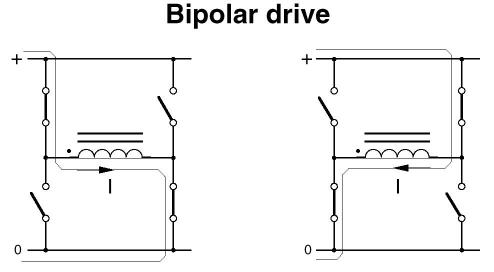
next: Brushless DC motors, with no commutator or brushes; wherein the surrounding magnetic fields have their polarities switched. Below: H-bridge for switch current direction through brushless DC coil.
http://www.ericsson.com/microe/apn_ind.html
http://www.microchip.com/stellent/idcplg?IdcService=SS_GET_PAGE&nodeId=2125¶m=en542235
How two electro-magnets opposite each other on freescale can be controlled by one H bridge dividing the coil into two parts, with radial currents in opposite directions...
Need spreadsheet of clock-down coils across timing see microchip site:
BLWS235D-36V-4000-1024SI Ana Auto with ENC-E211014250-GHI encoder on 3rd level of NBS Metro shelving in middle of 097
Braking vs turning off: stop sequence; make 3 Ns in a row
Hall Effect rotary encoder for actual position... factoring in actual position in controller