|
|
 |
 |
 |
 |
 |
 |
 |
 |
 |
 |
 |
 |
 |
Input / Output System and CalibrationGeneral Organization
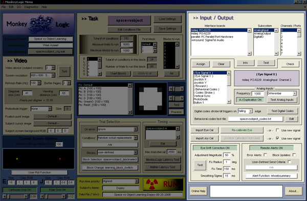
General Organization of the I/O SystemThe I/O system is responsible for monitoring eye-position and joystick-position, delivering reward, sending event-markers to a separate acquisition system, and delivering electrical stimulation or TTL pulses. A data acquisition (DAQ) board is useful for these functions. National Instruments PCI boards were used in the development of this software; DAQ boards from other vendors may work, but have not been tested. Hardware drivers provided by the manufacturer must be installed, and the MATLAB Data Acquisition Toolbox must be installed.
An input or output is defined by the software driver and associated board (piece of installed hardware), the subsystem (analog in, analog out, digital i/o), and the channel (if analog) or port + line (if digital). The assignment of specific functions (e.g., eye-signal x and y inputs or reward delivery) to particular channels or lines is determined by the assignments made in the main menu. To make an assignment, select the signal in the list-box (e.g., "Joystick X"), and select the board, subsystem and channel or line(s) in the boxes above. Finally, press the "assign" button. Pressing the "check" button will test the ability to properly initialize these assignments, turning green if successful.
Input / Output Assignment GuidelinesSeveral guidelines should be followed when making I/O assignments:
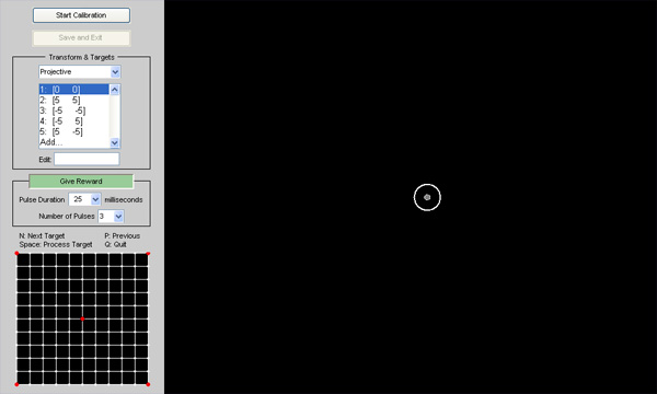
I/O menu settings are described in more detail on the main menu page. The default parameters for data acquisition and output are relatively minimal and should work on nearly any DAQ. However, if there are problems making I/O assignments, the properties of the DAQ system can be set manually by editing the header section of initio.m. See the literature for your specific hardware, and consult the MATLAB DAQ toolbox documentation. Input CalibrationThe eye- and joystick-signals can be used raw (pre-calibrated) or can be calibrated as needed. To calibrate a signal, click on the "Calibrate Eye-Position" or "Calibrate Joystick" button on the main menu. This will launch a new window with options for selecting the screen coordinates (in degrees) used for calibration and the option to deliver reward upon accepting each calibration point. Clicking on the main figure to the right will display a grid and allow the selection of a calibration point with the mouse.
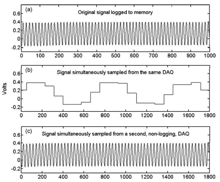
To begin calibration, press the "start calibration" button. The subject's display will show a single fixation point corresponding to the point visible on the control screen. Once calibration has begun, hitting the space bar will accept the current eye or joystick voltages as corresponding to the current point (actually, one hundred milliseconds of data beginning about 250ms before the space bar is pressed will be averaged, in order to prevent late deviations from skewing the intended values). Hitting "n" will display the next point and "p" will display the previous point, as dictated by the list shown to the left. Once calibration is complete, hit "q" and then press "save & exit." This calibration can then be saved in the full configuration file along with all the other task parameters in the main menu (by pressing "Save" in the main menu or by launching the behavioral task, which also saves the current configuration). Eye and / or joystick position can also be calibrated from within a task. To activate calibration, hit the [Escape] key and wait until the task pauses between trials. If eye or joystick signals have been defined in the main menu I/O panel, you will be given the option to press [e] or [j] to calibrate these inputs, respectively. Analog Input DuplicationIn order to allow MonkeyLogic to use analog signals both for real-time experimental control and for offline storage for later analysis, DAQ cards such as those from National Instruments must be used in two incompatible modes. In the first mode, for real-time behavioral control, analog signals are sampled from the DAQ card as fast as possible, at irregular intervals, limited only by the intervening computations for stimulus presentation, control screen updates, and target checking. Here, the DAQ card is left in a "free running" state, in which the most recent sample is queried over and over. In the second mode, the DAQ card is set to acquire analog data samples at regular intervals (e.g., 1000 Hz), so that these signals can be viewed and analyzed offline for later behavioral data analysis. In this strictly clocked mode, the DAQ cards only upload data in "chunks" every 20 to 50 milliseconds. This limits the frequency with which one can observe behavior to 20 to 50 Hz, rather than the 1 kHz which is generally the goal of "real-time" behavioral control.
From: Asaad & Eskandar, Achieving Behavioral Control with Millisecond Resolution in a High-Level Programming Environment For this reason, the solution MonkeyLogic has adopted is to employ two analog cards: one for real-time sampling in a free-running mode, and another for clocked data acquisition to be used offline. While requiring a bit of extra expense, this is nonetheless currently the best solution given the underlying hardware limitations. To enable this feature: 1) Install two identical DAQ boards, and split the analog signals into them so that each signal feeds into the analogous input on each board. 2) Enable "Analog Input Duplication" on the main menu. 3) Assign all of the analog inputs two one of the two boards. The second, identical DAQ will automatically be detected and used appropriately.
|
| This site last updated: May, 2014 | © 2008-2014 |