Main Menu
Overview
Video Submenu
Task Submenu
I/O Submenu
(Additional I/O Details)
NEW! MonkeyLogic User's Forum
Overview
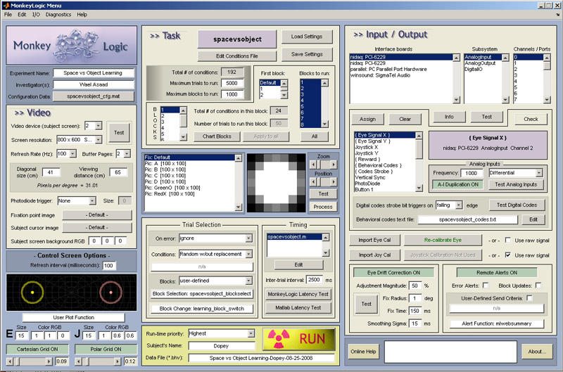
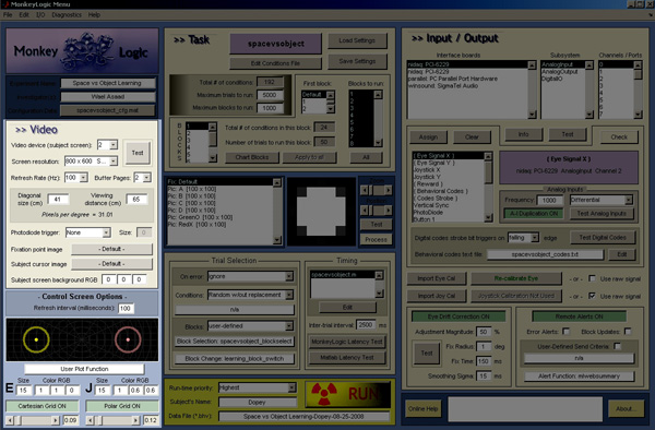
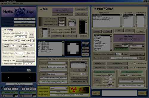
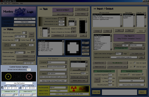
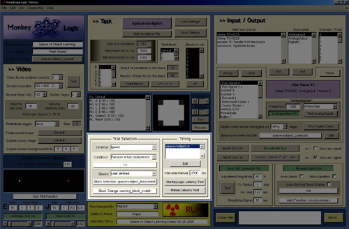
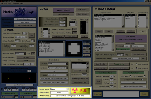
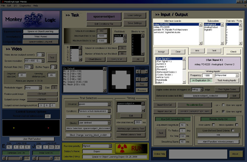
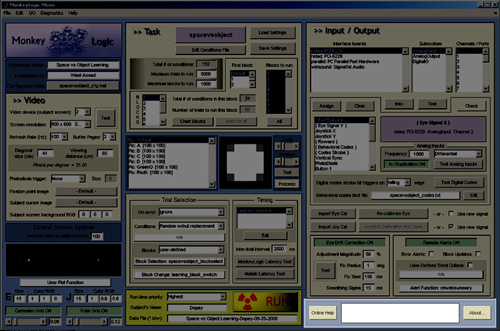
The main menu is launched by typing "monkeylogic" at the command prompt. It is divided into 3 primary sections: Video, Task, and Input / Output. Many of these options become active only once a conditions file is loaded (by clicking on the button next to the "Task" header, which here has loaded a conditions file titled "spacevsobject"). Changes made to any of the options, except "data file", can be saved and will be loaded automatically the next time the same conditions file is loaded. Running the primary (control) monitor in a video mode with at least a resolution of 1280 x 1024 is optimal in order for this menu to fit wholly into the screen.
Important: In order for the menu to accept typed input into any field, "enter" must be pressed after typing that input.
Menu Components
Video Submenu
This submenu is used to set the parameters for video display on the subject's screen (e.g., device number, screen resolution, refresh rate, etc) and to set parameters for the appearance of the control screen (seen by the experimenter, not the subject).
Subject Screen Settings
- Video Device (subject screen): This pop-up list will display the numbers associated with the video devices on the current system. Usually the highest numbered video device refers to the secondary screen.
- Screen Resolution: A range of resolutions from 640 x 480 to 2048 x 1536 is available (depending on hardware). As always, lower resolutions allow higher frame rates.
- Frame Rate: The subject screen (as determined by the video device, selected above) must be capable of updating at the frequency and resolution selected.
- Video Test: Displays a full frame animation at the selected settings; may take several seconds to initialize. The empirically-measured frame rate will be displayed in the message box after the test (it may be lower than the requested rate if the video card is not capable of updating at the selected settings).
- Diagonal Size: Enter the diagonal screen size (in cm) of the subject's monitor.
- Viewing Distance: Enter the distance (in cm) from the subject's eyes to the monitor.
- Pixels per degree: This value is calculated based on the viewing distance, screen size, and screen resolution.
- Photodiode Trigger: A photodiode trigger is a small square in one corner of the screen which flashes on-and-off in synchrony with the presentation or extinguishing visual stimuli (though not necessarily in-phase with those stimuli). Typically, a photodiode is placed over that region of the screen, and the photodiode and flashing square are then occluded from the subject's view (e.g., with electrical tape). The photodiode, when recorded to a separate acquisition system, will allow millisecond timing of display events (removing uncertainty about phase relative to refresh-rate). One should keep in mind that there will be a fixed delay between an on-screen stimulus and the photodiode event which depends on their relative positions along the scan-pattern of the display. The use of a photodiode is not necessary because the software can sense and time-stamp the screen-flip itself. However, this option is available as a back-up, and also to allow the accuracy of these time-stamps can be assessed directly if needed.
- Photodiode Size: For technical ease, will be rounded-down to the nearest multiple of four pixels.
- Fixation point image : Allows the selection of an image file (jpeg, bitmap, or gif) for use as the "fix" object.
- Subject cursor image: Allows the selection of an image file (jpeg, bitmap, or gif) for use as the joystick cursor which is visible to the subject once "showcursor(1)" is called in a timing script.
- Subject screen background color (RGB ):
Sets the background image color of the subject's display.
Built-in objects (such as "fix", "crc" and "sqr") will incorporate this background color into the image. The control screen representation below these settings (where the eye- and joystick traces & targets are shown) will turn the color of the selected background to give a broader view of the selected hue. However, only the subject screen will have this background color during task execution; the control screen will always maintain a black background.
Control Screen Settings
- Control Screen Update Interval: The desired approximate time, in milliseconds, between updates of the control screen (i.e., how fast the subject's behavior trace is updated). A usual value here is ~50 milliseconds.
- User Plot Function: The name of the Matlab function that will draw to the space normally occupied by the reaction time histogram on the control screen.
- Eye-Trace and Joystick Trace size: These are entered into the boxes immediately to the right of the large "E" and "J" for Eye-Signal and Joystick, respectively. This value determines the size of the marker used on the control-screen (not subject screen) to follow in real-time the position of the eye-trace or joystick during an experiment. It does not influence the size of the target ring in either case (this will be adjusted on-line to reflect the target diameter as defined by calls to eyejoytrack in the timing script).
- Eye-Trace and Joystick Color: These values (between 0 and 1) will determine the color of the traces and the target rings (which will be dimmer, but the same hue). The RGB colors should be entered in the three boxes adjacent to the size edit box, which itself is just to the right of the large "E" and "J" for Eye-Signal and Joystick, respectively.
- Polar and Cartesian Grids: The brightness of the grids (1-degree spacing) to be drawn on the control screen's background can be adjusted here.
Task Submenu
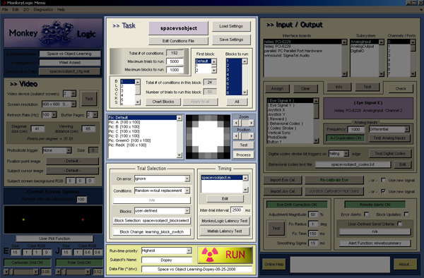
This submenu is used to select the behavioral task (by selecting the relevant conditions file), and to control task-related parameters such as which blocks to run, how many trials per block, and what to do in the case of a behavioral error (e.g., repeat that condition immediately). Several important buttons are located at the top of this panel:
- Conditions Selection Button: Located next to the "Task" header, this button loads a conditions text file, populates the associated menu controls, and activates many options. Basically, this button loads an experiment.
- Edit Conditions File: This button opens the selected conditions file in a text editor (Notepad). The conditions file will automatically be re-loaded after edits have been completed so that those changes may take effect.
- Save settings: Saves all the options (except data file name) as currently set in a configuration file (named as the conditions file but with the suffix "_cfg.mat"). These options will then be re-loaded automatically each time that conditions file is selected.
- Load settings: Allows one to load the settings from a configuration file associated with a different conditions file from the one currently selected.
General Task Settings and Block Selection
- Total # of conditions: Displays the total number of conditions found within the selected conditions file.
- Maximum trials to run: Determines when the task will stop if not manually terminated.
- Blocks to run: Only the blocks selected here will be used during task execution.
- Maximum blocks to run: Determines the total number of blocks (not block numbers) to be run; the task will end once this number of blocks has executed (or the "maximum trials to run" value has been reached, whichever comes first).
- Block #: This list-box displays all of the available blocks. The number of trials to run for the currently selected block can be set to the right of this list.
- Total # of conditions this block: Displays the total number of conditions associated with the selected "Block #"
- Chart Blocks: Opens a new figure with a condition vs. block chart with asterisks indicating which conditions appear in which blocks. See Charting Blocks & Conditions.
- Number of trials to run this block: Edit this value to determine the number of trials to be run when the block selected to the left (in the "Block #" box) is in-effect. Note that this option is disabled if a user-defined block-change function is used (because that function will determine when to switch blocks).
- Apply to all: applies the entered number of trials to play per block to all blocks.
Stimulus Pane
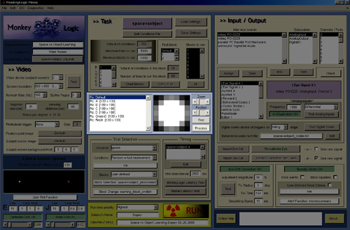
- Stimulus list-box: This list is populated with the unique stimuli found in the selected conditions file. Selecting an item here will cause it (or a representation of it) to be displayed to the right.
- Zoom: This slider controls the size of the stimulus (in the menu, only - not during task execution).
- Position: This slider controls position along a stimulus (useful for one-dimentional stimuli, i.e., sound and stimulus objects, and for movies, where it scrolls through frames).
- Test: Displays or plays the selected TaskObject (warning: stimulation will be delivered if a STM or TTL object is selected). Visual objects will be presented in the center of the screen regardless of where they will appear during an actual task. Movies will play alternately forwards then backwards at the currently selected video settings. Pressing any key will terminate the stimulus.
- Process: This option when depressed will scan the file for visual stimuli (pictures and movies) and pre-process them to save time during the inter-trial-intervals. This is especially useful when a task contains large or long movies that could potentially delay the start of the subsequent trial due to the processing time required. Each stimulus file is used to generate a speed-optimized file (for example, ""A.jpg" will generate "A_preprocessed.mat"). The progress through these stimuli will be shown in the message box at the bottom-right of the menu. Once these optimized files have been created, this button will turn green. Running the task will now use those preprocessed files instead of the original ones (as long as this button remains depressed). On subsequent sessions, those preprocessed files will still be available, so there is no need to re-process them. However, if the contents of a particular file have changed (e.g., there is a file called "gratingmovie.avi" that contains a different grating movie on different days), this button should be untoggled and then re-toggled to re-create the optimized files. For this reason, when loading a conditions file and configuration parameters with a previously pre-processed set of stimuli, this button will appear red to indicate that if optimized files are present, they may need to be updated.
- Save full movies to BHV file: When checked (the default), the full movies will be written to the header of the BHV file. This allows the ability to replay trials with movies exactly as they occurred from the data file alone. However, this can sometimes lead to delays in starting a task and very large file sizes, particularly when there are many movies or when the movies are large. Therefore, unchecking this option will result in only the first frame of each movie being saved to the BHV file.
Trial Selection Settings
- On Error: What to do if the subject makes an error.
- Ignore will simply disregard errors when the next condition is selected.
- Repeat immediately will cause the same condition to be played repeatedly until the correct response is chosen (i.e., trialerror(0) has been set by the timing file).
- Repeat delayed will throw that condition into the queue, but at a later point in the block; this can happen an indefinite number of times for a given condition. If a particular condition is repeatedly performed incorrectly, increasing numbers of copies of this condition will "pile-up" later in the block, though still interspersed with whatever other conditions still remain to be played.
- Conditions: Determines the method used to select the next condition.
- Random with replacement causes the next trial's condition to be selected randomly, without regard to which conditions have already been used.
- Random without replacement will randomly choose the next trial's condition but will exclude those trials already used; if the block length exceeds the total number of conditions available in that block, the available conditions from which to select will be replenished each time they are exhausted.
- Increasing and Decreasing simply choose the next condition in numerical order, rising or falling as appropriate. The condition numbers will "wrap" when the end or beginning of the condition list has been reached.
- User-defined allows the writing of a matlab function to determine how conditions are selected. This is useful to enact particular rules about how certain conditions should follow others, or how the selection of certain conditions preclude others, for example. This function should be contained in a typical m-file and should expect the TrialRecord structure as input, and should return a single scalar, the condition to-be-run. If a value of -1 is returned, this will indicate that the block has ended, and a new block should be selected.
- Blocks: Identical in logic to Conditions, above. Here, however, the user-defined option should return the desired block-number as output. If a value of -1 is returned, this will indicate that the task has been completed, and task execution will end. Note that a user-defined block-selection function will be run on each trial to determine if the a new block should be chosen. A block-selection function is useful, for example, when behavior must reach a certain threshold before allowing the next block to proceed.
- Condition-Selection Function: The name of the m-file containing the user-defined condition-selection function, if applicable. This function must be located in the experiment's base directory. This function is expected to return the condition number to be played next. Returning -1 indicates that this block is complete and a new block should be chosen according to the method selected above. This function, like all user-provided functions, has access to the TrialRecord structure, which provides information about the subject's performance, conditions- and blocks-played, thus far.
- Block-Selection Function: The name of the m-file containing the user-created block-selection function, if applicable. This function must be located in the experiment's base directory. This function, if specified and Blocks are set to be selected in a "user-defined" fashion, is called after the completion of each block, and is passed the TrialRecord structure. Your function should return the number of the new block to run (simple scalar value). This function is called when a block is determined to be complete based upon the parameters set above (e.g., number of trials to run within each block). In order to prescribe when a block should change from within an m-file, use the "Block-Change Function" described next. Note: if the Block-Selection Function is set to the same file as the Block-Change Function (see below), this indicates that the Block-Change Function returns not simply a block-switch flag, but actually determines the next block to be run (i.e., a non-zero flag indicates that a block-switch should occur, and the value of this flag is itself the number of the next block to be played).
- Block-Change Function: This user-created function, if specified, is called after every trial to determine whether a new block should be initiated. It is passed the TrialRecord structure, and should return a value of "1" to change blocks, or "0" to continue the current block. The next block will be selected in the usual manner, according to the options described above. However: if the Block-Selection Function (above) is set to the same file as the Block-Change Function, this indicates that the Block-Change Function returns not simply a block-switch flag, but actually determines the next block to be run (e.g., return "3" to switch to running the third block). This feature allows one m-file to control both when a block switches and which block is selected next.
- Timing Files: This list-box displays the timing files used by the current conditions file. Pressing edit will open the selected timing file in the Matlab editor (if Java is enabled).
- Inter-Trial Interval (ITI): Enter the desired inter-trial interval (in milliseconds). After house-keeping operations and the preparation of stimuli for the upcoming trial, a timer will subtract the used time and wait to initiate a new trial until the specified ITI time has elapsed. Note, however, that the actual ITI may be longer than this value if the chosen ITI is too short (less than a few hundred milliseconds, in most cases), such that these house-keeping and stimulus preparation events have not yet completed. Specifically, several hundred milliseconds are reqiured between trials in order to load / generate images and store them in video RAM, as well as to write data to the behavioral (.bhv) file and to update stats on the control screen. The delay will be longer with more or larger stimuli to process, and is variable in exact length. If the selected ITI (as entered in the main menu) is very short (e.g., under a few hundred milliseconds) and there are many or large stimuli to be processed, the actual ITI might exceed the desired time. If this happens, a warning will be displayed. To speed up the handling of stimuli during the ITI, use the "process" option.
- MonkeyLogic Latency Test: Runs a benchmarking trial that calculates the temporal latencies between successive behavioral signal samples both during static picture presentation and during movie presentation.
- MATLAB Latency Test: Performs several hundred-thousand empty-loop cycles in each of the three process priorities available in Windows, and presents a figure with statistics about each. The mean latency in the highest priority setting is expected to be at most 0.02 ms (cycle speed of 50 kHz). Actual performance during an experiment will be slower, but still should be faster than 1 kHz. Notice that the difference in priorities affects not so much the mean latency, but the maximum latency. Setting a high priority during data collection will ensure that sporadic high latencies are minimized. See the methods papers (particularly the first reference) for more specific details about the effects of setting different process priorities.
Launch Pane
- Subject's Name: This name will be stored in the data file, and will be incorporated into the data file name (if a data file name has not already been entered).
- Data file: The name of the behavioral data file (will be ".bhv" format). If a data file with the same name exists, a suffix will be appended to avoid over-writing the existing file. This data file contains information about each condition run, the block numbers, the behavioral errors, and the intra-trial event-markers. In addition, the conditions file structure will be saved, picture images loaded from a jpeg, bitmap, or gif file will be saved, and the behavioral code descriptions associated with each event-marker will be saved. These data allow an experiment to be reconstructed almost entirely from the data file alone.
- Run-Time Priority: Sets the process priority to one of the three levels allowed by Windows (Recommended to be set to "highest" for data collection).
- RUN: Starts a task running. This button becomes active once a conditions file is selected and once a data file has been specified. Java must be disabled to run a task.
Input / Output Submenu
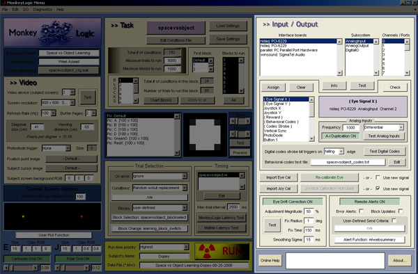
The I/O submenu is used to make assignments between channels and lines on the DAQ card and specific MonkeyLogic functions, such as eye-signal tracking and reward delivery. In addition, the settings for signal-calibration and eye-drift correction can be accessed here.
An I/O assigment is made by selecting that signal in the scroll list near the middle of this panel and selecting the appropriate board-subysystem-channel/line in the upper three boxes, then pressing the "assign" button. See below for specific information on the I/O menu options. Also refer to the I/O Details page for more comprehensive information about making I/O assignments and the guidelines which should be followed.
I/O Assignments
- Interface Boards: This listbox displays the DAQ boards found on the current system. In some cases, a board will be listed even when it is not physically attached if the associated driver is installed; however, no subsystems or channels will be shown for that board.
- Subsystem: This listbox shows the available subsystems on the selected board. These are usually of the type: Analog Input, Analog Output, and Digital In/Out.
- Channels / Ports: The assigned numbers of the available channels (on an analog subsystem) or ports (on a digital subsystem) are displayed. The number of lines available on a given digital port, and whether those ports are input, output, or user-configurable, depend on the specific hardware being used.
- Set (I/O Assignments): The following block lists each type of possible input or output and allows assignments to be made by pressing the respective "set" button when the desired I/O pathway has been selected, above.
Thesubsystem assignments allowed for each type of data stream are listed here:
| Eye Signal X and Y |
Analog Inputs |
| Joystick X and Y |
Analog Inputs |
| Buttons & Levers |
Analog or Digital Inputs |
| Reward |
Analog Output or Digital (line-selection dialog will appear if digital) |
| Digital Codes (for event markers) |
n digital lines to be chosen from among those available on the selected port (dialog will appear) |
| Digital Codes Strobe |
One digital line to be chosen from among those available on the selected port (dialog will appear) |
| Stimulation |
Analog Outputs |
| TTL |
Digital |
- Check (Assignments): This button will initialize the I/O system as configured through the menu. If any errors are encountered, the button will turn red. If the initialization is successful, the button will turn green.
- Test (I/O): This button will pull up a new window which will either produce a signal (sine wave for analog output or square wave for digital out) or show the voltages on the selected channel of the selected subsystem of the selected board.
- Analog Input Duplication: As described in the Temporal Precision and Input/Output Calibration sections, using two duplicate DAQ cards allows for much faster sampling of the analog inputs. If two such cards are detected, this option will be available for activation.
- Analog Input Frequency: The frequency at which to acquire analog data (samples per second).
- Analog Input Type: Select the input type which corresponds to the manner in which analog inputs are connected (default is "differential").
- Test Analog Inputs: This button empirically tests the analog input speed (as long as at least one valid AI assignment has been made). With two DAQ boards present and analog input duplication (above) active, the measured rate will be significantly faster than the rate using only one board for analog input acquisition (the reasons for this are explained in the Temporal Precision section). The first value ("effective sampling rate") reflects how many non-stationary data points were returned, whereas the second value ("maximum possible sampling rate") reflects how many data points were returned in total. Important: To get accurate and informative results, the analog inputs should be connected to a rapidly-varying signal (e.g., sine-wave oscillating ~ 1 kHz).
Behavioral Codes (EventMarkers) Settings
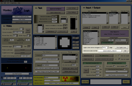
- Strobe Bit Trigger-Edge: Digital codes (i.e., event markers) will use either a rising or falling strobe bit, depending on the configuration of the acquisition hardware (e.g., the Plexon "MAP" system and standard parallel ports trigger on the falling edge, whereas the Cyberkinetics "neuroport" system triggers on the rising edge).
- Test Digital Codes : Pressing this button tests the digital codes output, sending 10 sets of numbers via the selected digital output using the selected strobe bit edge. Each set of numbers sent contains 20 through 2n in order to test each bit in sequence (where n is the number of lines allocated minus one).
- Edit Codes File : This button opens the text file (in Notepad) which lists each code number with its associated description. The descriptions (of the codes used during a given task run) are saved in the BHV file in order to facilitate future reconstruction of task events, even if this file is lost.
- Behavioral Codes text file: This button sets the text file to be used as a source for the descriptors of the code numbers used as eventmarkers. These descriptors will then be stored in the data file to prevent future ambiguity regarding the codes' meaning.
Signal Calibration Settings
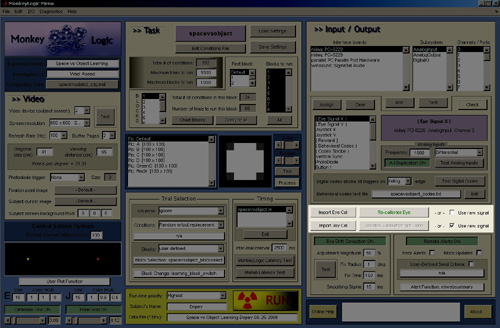
- Load Eye Cal(ibration): Loads a previously created eye-signal transformation matrix from any configuration file.
- Load Joy Cal(ibration): Loads a previously created joystick signal transformation matrix from any configuration file.
- Calibrate Eye Position: Opens a new window to allow calibration of the eye-signal input.
- Calibrate Joystick Position: Opens a new window to allow calibration of the joystick input.
- Use Raw Signal: Will by-pass the respective tranformation matrix and use the acquired voltages directly to determine screen position (assumes the signals are pre-calibrated).
Eye Drift Correction Settings
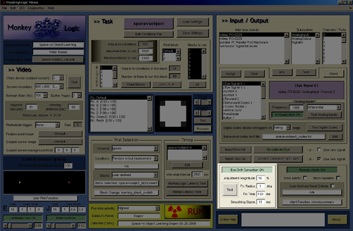
- Eye Drift Correction On/Off : This button will toggle the on-line eye-drift correction feature on or off. It requires the parameters below and works approximately as follows: After each trial, saccades are detected as events in which the eye velocity (convoluted with a gaussian whose std is defined by "smoothing sigma") is greater than two standard deviations above baseline. Fixations are identified as epochs between saccades of at least "fix time" ms in duration. Any fixations occuring within "fix radius" degrees of a task object used on that trial are assumed to have been intended to land on the center of that object. This difference defines the drift error. The drift error is corrected by a percentage, given by "adjustment magnitude," then these adjusted points are fed back through the calibration transformation to correct for the measured drift.
- ...Adjustment Magnitude: For a given error between measured and desired fixation location, the percent of this error to correct after each trial. A value less than 100% is recommended to achieve stable behavior (the default is 50%).
- ...Fix Radius: The radius within which a detected fixation will be assumed to have been intended to land on a task object.
- ...Fix Time: The minimum time between saccades necessary for an epoch to count as a fixation.
- ...Smoothing Sigma: The standard deviation of the gaussian kernel used to smooth the recorded eye data for the detection of saccades. The ideal value here is dependent upon the signal-to-noise characteristics of the particular eye-tracking system in-use.
- Test Eye Drift Correction : This button will cause 3 seconds of eye data to be acquired, onto which the selected settings will be applied so that the user can assess the accuracy of saccade detection in the resulting figure.
Remote Alerts & Web Updates Settings
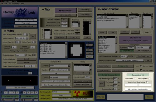
- Remote Alerts On/Off : This button will toggle the remote alerts feature and allows setting the type of alert (brief text alert vs web page update) depending on the type of alert function selected. The "Error Alerts," "Block Updates," and "User-Defined Send Criteria" are only applicable to text alerts.
Message Pane
- Online-Help: Pressing this button will open a web browser and bring you to this site.
- About...: Displays the revision date of the current copy of MonkeyLogic
- Message Box: Messages, warnings, and errors will appear in this box in relation to menu-based activities (e.g., loading a conditions file).
|